Alien DAC v1.1 Construction Thread
Jan 3, 2007 at 6:02 PM Post #541 of 1,562
Quote:

Originally Posted by villekille /img/forum/go_quote.gif
..my amp uses a 20V power supply, isn't this too much for the alien dac? aren't the regulators getting too hot?


the reg10x regulators are rated for a maximum input voltage of 12V ! You may use a simple 7808 regulator to drop the voltage
 
Jan 3, 2007 at 9:12 PM Post #542 of 1,562
Quote:

Originally Posted by steinchen /img/forum/go_quote.gif
the reg10x regulators are rated for a maximum input voltage of 12V ! You may use a simple 7808 regulator to drop the voltage


Indeed, but I believe the REG101's only see the voltage between V+ and GND, they should be able to cope, though may get quite hot. The BUF634 can handle 36V, and it's the only part that sees the full 20V so you should be fine.

I'm not an expert, but I'm thinking that putting a regulator on V+/V- will interfere with the virtual ground and generate an unacceptable DC offset in the range of several volts. Beware if you try it. However, I believe you could use a 5V reg to drop the voltage from the amp's + rail to GND, and use the 'external supply' option. But why when the spec'd parts will handle it fine
smily_headphones1.gif
.
 
Jan 4, 2007 at 4:20 AM Post #543 of 1,562
How did you come up with the value of 4uf-47uf for CL/CR please? Oh nevermind...I used 1uf Wima MKS2 caps for CL/CR and it sounds fine! I will try the blackgates when they get here from parts connexion...whenever that will be...eh?!?
 
Jan 8, 2007 at 4:34 PM Post #544 of 1,562
My 46 year old eyes can't see SSOP-28 at all. I soldered the PCM 2702 in as much by feel as anything else.

After a second going over with solder wick, my PC recognized the DAC. The board still has problems that I couldn't see even with stacked reading glasses. Using the super macro mode on my Olympus found three or four solder bridges.


P1010022_edited.JPG
 
Jan 8, 2007 at 10:24 PM Post #545 of 1,562
That board needs some cleaning! Use alcohol(the one from the pharmacy :p) and an old toothbrush and give the board a good scrub. you have lots of flux there. And if you have some solder flux, reheat the PCM pins with some flux, that should take care of those bridges. You can also reheat your other solder joints with flux.
 
Jan 10, 2007 at 3:19 PM Post #546 of 1,562
Got a question,
I can get most of the parts easily, but i'm having a hard time finding a cap for :

C11 Ceramic 1µF-22µF. 0805 package

my problem is that i cant find one thats within those values (1uf-22uf) is there anything i can replace it with ?
 
Jan 10, 2007 at 5:25 PM Post #547 of 1,562
I've read through the threads and AFIK no one tuned the input filter or ran a SPICE simulation. You can use just about any ceramic 0805 cap and the DAC will work.

I'm using a 150pF MuRata ERB series cap for C1. Mouser Part number 81-ERB21BC1H151JDX1L

The ERB cap might do a better job keeping HF noise out of the downstream power. I don't see why C1 needs to be >> 1µF since C2 is 680µF.
 
Jan 10, 2007 at 5:27 PM Post #548 of 1,562
Quote:

Originally Posted by MASantos /img/forum/go_quote.gif
That board needs some cleaning!


Yes it did. No point in giving it a good cleaning until after I fixed the bridges.

The bridges are cleaned up and the +5V short is gone, and I've got output. I'm going to solder in CL, CR and C2 and see how it sounds
580smile.gif
 
Jan 10, 2007 at 9:08 PM Post #550 of 1,562
Quote:

Originally Posted by jornterpstra /img/forum/go_quote.gif
Got a question,
I can get most of the parts easily, but i'm having a hard time finding a cap for :

C11 Ceramic 1µF-22µF. 0805 package

my problem is that i cant find one thats within those values (1uf-22uf) is there anything i can replace it with ?


Digikey 490-1691-1-ND
 
Jan 10, 2007 at 9:16 PM Post #551 of 1,562
Yesterday my Alien DAC went Alien Dead.....
frown.gif


i was experimenting with something for my school project and
accidentally i misconnected the alien dac output and i burned it!
now the project went back...but who cares about the project??? i lost my precious dac!!!

these days i'm going to start the "aLiEn DaC ReSuRrEcTiOn PrOcEdUrE"
I would like we all call it that way if it is not copyrighted!
icon10.gif


Resurrection Guide:

If you dac is totally dead like mine and the problem is the IC do the following...take a very sharp knife (knifes with very small teeth are preferable)
remove the crystal and the near capacitors, put the knife to the pins as close
as you can to the plastic package of the IC and start carefully cutting the pins! after cutting the one side do the same to the other (or somehow use your soldering iron to remove the other side), after you finish put flux to the surface and gently try to remove the leftover pins from the pads and the excess solder..Hopefully all pads stay intact! i lost only one pad...pad 12 which it's not connected anywhere...

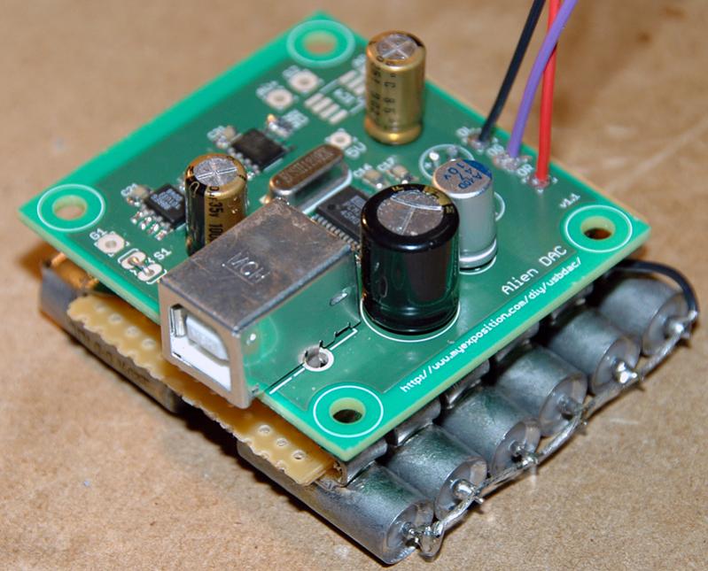
The following photos shows my alien dac after removing the IC...


sorry for the quality...it's from my mobile phone.
Things are not as worse as they look like pads are very clear and and
you can solder the IC like before...(and maybe better)

Achtung! - Attention!
icon10.gif


Special care is needed when you cut the IC, because you can easily drift out pins and pads
by cutting them careless! i'm not responsible if you try and fail with the prescribed way
and it is preferable to try it ONLY if you think that your board is for the garbage can.


anyway! wish me luck!
icon10.gif
 
Jan 10, 2007 at 10:03 PM Post #553 of 1,562
Quote:

remove the crystal and the near capacitors, put the knife to the pins as close
as you can to the plastic package of the IC and start carefully cutting the pins! after cutting the one side do the same to the other (or somehow use your soldering iron to remove the other side), after you finish put flux to the surface and gently try to remove the leftover pins from the pads and the excess solder..Hopefully all pads stay intact! i lost only one pad...pad 12 which it's not connected anywhere...


Screw that.
I had another forum member send a non working alien dac to debug and sure enough had soldered the IC on backwards.
All it took was a a big blob of solder (to heat all of the pins on one side of the chip) a little prying and another big blob of solder (on the second side) to remove the chip.
I did not lose a single pad.


Quote:

All you did was unplug it??


Read much?
wink.gif
 
Jan 10, 2007 at 10:54 PM Post #554 of 1,562
ok misterX...but still it's an option! for bigger ICs maybe..where you can't
easily heat all the pins! think of square chips!
icon10.gif


Quote:

Originally Posted by picklgreen /img/forum/go_quote.gif
Wait, how did you kill your DAC's chip again? All you did was unplug it??


i was playing with a board connected to the alien dac and i had forgotten that alien dac was on the usb and just burned the output..that's all!
rolleyes.gif


so..we must be careful with the experiments or you're going to end up
like me! my school project blown away..until i fix my dac.
 

Users who are viewing this thread

Back
Top