Guess I'll have to reserve the XLR inputs for future use; perhaps an updated Gungnir (with Yggdrasil tech).
Any idea wether something like the PonoPlayer's balanced out (if better than its SE) would translate to improvements via the Carbon's SE input compared to straight SE to SE?
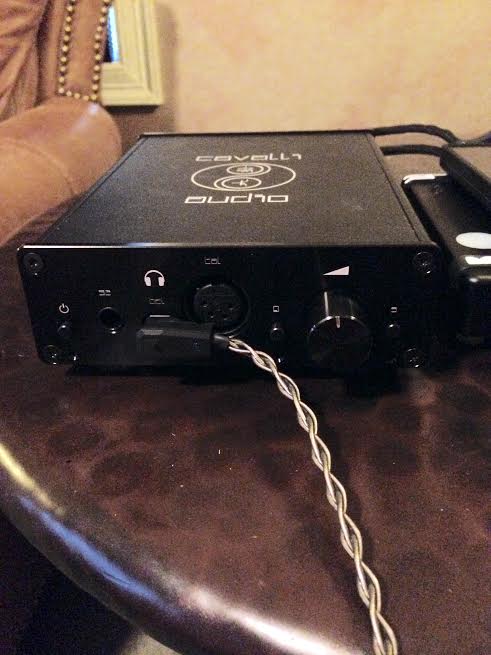
Also (just curious), would rca to xlr cause any damage?
As far as i understand it the Pono has true balanced output in the form of 2x 3.5mm TRS ouputs (1 for each channel). Therefore you should be able to connect that into the corresponding balanced 3 Pin XLR inputs of the Carbon. In balanced mode the trs connector presumably would be wired as +, - and separate ground on each channel?
I dont have a Pono myself so can say for sure.
I don't think you could use the same cables for the iDSD because its 3.5 mm cable runs unbalaced and carries both left and right channels in one cable.
I feel like cables have no effect unless they're either interconnects, internal cables, or cables to the headphone/speaker. USB cables just transfer solid 1's and 0's and power cables can't make the power any better than the crap copper ones in the walls of your house. Once the electricity has been turned into an analog signal through the DAC, then maybe different cables have their own sound, but I'm just making this up based on my opinion.
I, for one, may end up getting some Cardas interconnects someday just because they look sexy as all get out to me. Otherwise any decent cable that isn't half tin should sound just about as good as any other, just with minor differences in tone or whatever.
Except USB cables don't really transfer solid 1's or 0's, they transfer a voltage difference that approximates 1's and 0's. In my hands-on comparisons they absolute can make a difference. The only digital cable that transfers "real" binary data is toslink, where the light is either on or off, but they have their own issues in implementation. I'd recommend that people try different USB cables (as well as other IC's and PC's) and see what works for them. Cheers!
Fascinating. So you're saying, sometimes the voltage differences are misread over USB? I know computers have pretty sophisticated self-error-correction maths, but... Interesting. Also could explain why an ODAC was extremely cable picky a few years back.
Except USB cables don't really transfer solid 1's or 0's, they transfer a voltage difference that approximates 1's and 0's. In my hands-on comparisons they absolute can make a difference. The only digital cable that transfers "real" binary data is toslink, where the light is either on or off, but they have their own issues in implementation. I'd recommend that people try different USB cables (as well as other IC's and PC's) and see what works for them. Cheers!
I have found this to be true in many different hobbies.
Non Head-fi Pro Tip: don't upgrade your suspension on your motorcycle if you don't want to be forced to spend thousands of dollars doing it to every bike you buy for the rest of your life! lol
@Pirakaphile, I personally think it is ignorance* that is bad for the pocketbook. The waveform responsible for '0' and '1' do not need to be perfect to ensure perfect reproduction. Think of it as square waves with a very sharp drop-off. That is the entire point of using a binary 'true-false' type system. Binary inherently means that there is only two options available, either 0 or 1. No room for a 0.9 or 1.1. I would be interested in reading a verified source suggesting that there is a discrepancy in the 'quality' of the 0 and 1 being transferred as I have not seen such an article. If the receiving circuit can identify the waveform, the reception of the signal will be, in the end analysis, perfect, regardless if the square waves look different (aka if the voltage difference is variable but still above the threshold). if the receiver misidentifies the digital data (aka digital data was lost), the loss is total and final. This means digital signals exhibit no functional degradation at all up to a certain threshold, but once the 'quality' falls beneath that threshold, there is no signal at all. this means that digital cables meeting the standard of compliance will either work or obviously not work with glaring flaws. There is no in-between. A USB compliant standard ensures that all certified USB cables meet specifications and conform to tested standards for performance. The only physical quality of the cable itself (other being defective) that can affect the performance of a USB cable would be length. for people who think about digital cables differently, their logic would then also apply to a multitude of other digital cables such as HDMI cables.
The host includes 15 kΩ pull-down resistors on each data line. When no device is connected, this pulls both data lines low into the so-called "single-ended zero" state (SE0 in the USB documentation), and indicates a reset or disconnected connection.
A USB device pulls one of the data lines high with a 1.5 kΩ resistor. This overpowers one of the pull-down resistors in the host and leaves the data lines in an idle state called "J". For USB 1.x, the choice of data line indicates of what signal rates the device is capable; full-bandwidth devices pull D+ high, while low-bandwidth devices pull D− high. The "k" state is just the opposite polarity to the "j" state.
USB data is transmitted by toggling the data lines between the J state and the opposite K state. USB encodes data using the NRZIline coding; a 0 bit is transmitted by toggling the data lines from J to K or vice versa, while a 1 bit is transmitted by leaving the data lines as-is. To ensure a minimum density of signal transitions remains in the bitstream, USB uses bit stuffing; an extra 0 bit is inserted into the data stream after any appearance of six consecutive 1 bits. Seven consecutive received 1 bits is always an error. USB 3.0 has introduced additional data transmission encodings.
A USB packet begins with an 8-bit synchronization sequence '00000001'. That is, after the initial idle state J, the data lines toggle KJKJKJKK. The final 1 bit (repeated K state) marks the end of the sync pattern and the beginning of the USB frame. For high bandwidth USB, the packet begins with a 32-bit synchronization sequence.
A USB packet's end, called EOP (end-of-packet), is indicated by the transmitter driving 2 bit times of SE0 (D+ and D− both below max) and 1 bit time of J state. After this, the transmitter ceases to drive the D+/D− lines and the aforementioned pull up resistors hold it in the J (idle) state. Sometimes skew due to hubs can add as much as one bit time before the SE0 of the end of packet. This extra bit can also result in a "bit stuff violation" if the six bits before it in the CRC are '1's. This bit should be ignored by receiver.
A USB bus is reset using a prolonged (10 to 20 milliseconds) SE0 signal.
USB 2.0 devices use a special protocol during reset, called "chirping", to negotiate the high bandwidth mode with the host/hub. A device that is HS capable first connects as an FS device (D+ pulled high), but upon receiving a USB RESET (both D+ and D− driven LOW by host for 10 to 20 ms) it pulls the D− line high, known as chirp K. This indicates to the host that the device is high bandwidth. If the host/hub is also HS capable, it chirps (returns alternating J and K states on D− and D+ lines) letting the device know that the hub operates at high bandwidth. The device has to receive at least three sets of KJ chirps before it changes to high bandwidth terminations and begins high bandwidth signaling. Because USB 3.0 uses wiring separate and additional to that used by USB 2.0 and USB 1.x, such bandwidth negotiation is not required.
Though high bandwidth devices are commonly referred to as "USB 2.0" and advertised as "up to 480 Mbit/s", not all USB 2.0 devices are high bandwidth. The USB-IF certifies devices and provides licenses to use special marketing logos for either "basic bandwidth" (low and full) or high bandwidth after passing a compliance test and paying a licensing fee. All devices are tested according to the latest specification, so recently compliant low bandwidth devices are also 2.0 devices.
USB 3 uses tinned copper stranded AWG-28 cables with 90±7 Ω impedance for its high-speed differential pairs and linear feedback shift registerand 8b/10b encoding sent with a voltage of 1 V nominal with a 100 mV receiver threshold; the receiver uses equalization.[size=11.1999998092651px][127]SSC clock and300 ppm precision is used. Packet headers are protected with CRC-16, while data payload is protected with CRC-32.[size=11.1999998092651px][128][/size] Power up to 3.6 W may be used. One unit load in superspeed mode is equal to 150 mA.[size=11.1999998092651px][128][/size][/size]
Example of a Negative Acknowledge packet transmitted by USB 1.1 full-speed device when there is no more data to read. It consists of the following fields: clock synchronization byte, type of packet and end of packet. Data packets would have more information between the type of packet and end of packet.
regardless of how I feel about the subject, I recommend simply doing your own research or trying it for yourself rather than relying on other people's opinions (including my own) without reading up on background sources. not looking to start a debate or argument. (though if someone wants to privately discuss, feel free to PM me).
edit: ymmv, feel free to disagree (though preferably with an independent source)
yes, blinded side-by-side direct testing. I could not tell the difference, but I know we all have different ears, so ymmv.
edit: I know it is rude to tell others what they can or cannot hear, so that is totally not my intention. I am simply relaying why the subtle variations in voltage difference should not make a difference in audio quality for USB cables from a scientific point of view.
@Pirakaphile, I personally think it is ignorance* that is bad for the pocketbook. The waveform responsible for '0' and '1' do not need to be perfect to ensure perfect reproduction. Think of it as square waves with a very sharp drop-off. That is the entire point of using a binary 'true-false' type system. Binary inherently means that there is only two options available, either 0 or 1. No room for a 0.9 or 1.1. I would be interested in reading a verified source suggesting that there is a discrepancy in the 'quality' of the 0 and 1 being transferred as I have not seen such an article. If the receiving circuit can identify the waveform, the reception of the signal will be, in the end analysis, perfect, regardless if the square waves look different (aka if the voltage difference is variable but still above the threshold). if the receiver misidentifies the digital data (aka digital data was lost), the loss is total and final. This means digital signals exhibit no functional degradation at all up to a certain threshold, but once the 'quality' falls beneath that threshold, there is no signal at all. this means that digital cables meeting the standard of compliance will either work or obviously not work with glaring flaws. There is no in-between. A USB compliant standard ensures that all certified USB cables meet specifications and conform to tested standards for performance. The only physical quality of the cable itself (other being defective) that can affect the performance of a USB cable would be length. for people who think about digital cables differently, their logic would then also apply to a multitude of other digital cables such as HDMI cables.
The host includes 15 kΩ pull-down resistors on each data line. When no device is connected, this pulls both data lines low into the so-called "single-ended zero" state (SE0 in the USB documentation), and indicates a reset or disconnected connection.
A USB device pulls one of the data lines high with a 1.5 kΩ resistor. This overpowers one of the pull-down resistors in the host and leaves the data lines in an idle state called "J". For USB 1.x, the choice of data line indicates of what signal rates the device is capable; full-bandwidth devices pull D+ high, while low-bandwidth devices pull D− high. The "k" state is just the opposite polarity to the "j" state.
USB data is transmitted by toggling the data lines between the J state and the opposite K state. USB encodes data using the NRZIline coding; a 0 bit is transmitted by toggling the data lines from J to K or vice versa, while a 1 bit is transmitted by leaving the data lines as-is. To ensure a minimum density of signal transitions remains in the bitstream, USB uses bit stuffing; an extra 0 bit is inserted into the data stream after any appearance of six consecutive 1 bits. Seven consecutive received 1 bits is always an error. USB 3.0 has introduced additional data transmission encodings.
A USB packet begins with an 8-bit synchronization sequence '00000001'. That is, after the initial idle state J, the data lines toggle KJKJKJKK. The final 1 bit (repeated K state) marks the end of the sync pattern and the beginning of the USB frame. For high bandwidth USB, the packet begins with a 32-bit synchronization sequence.
A USB packet's end, called EOP (end-of-packet), is indicated by the transmitter driving 2 bit times of SE0 (D+ and D− both below max) and 1 bit time of J state. After this, the transmitter ceases to drive the D+/D− lines and the aforementioned pull up resistors hold it in the J (idle) state. Sometimes skew due to hubs can add as much as one bit time before the SE0 of the end of packet. This extra bit can also result in a "bit stuff violation" if the six bits before it in the CRC are '1's. This bit should be ignored by receiver.
A USB bus is reset using a prolonged (10 to 20 milliseconds) SE0 signal.
USB 2.0 devices use a special protocol during reset, called "chirping", to negotiate the high bandwidth mode with the host/hub. A device that is HS capable first connects as an FS device (D+ pulled high), but upon receiving a USB RESET (both D+ and D− driven LOW by host for 10 to 20 ms) it pulls the D− line high, known as chirp K. This indicates to the host that the device is high bandwidth. If the host/hub is also HS capable, it chirps (returns alternating J and K states on D− and D+ lines) letting the device know that the hub operates at high bandwidth. The device has to receive at least three sets of KJ chirps before it changes to high bandwidth terminations and begins high bandwidth signaling. Because USB 3.0 uses wiring separate and additional to that used by USB 2.0 and USB 1.x, such bandwidth negotiation is not required.
Though high bandwidth devices are commonly referred to as "USB 2.0" and advertised as "up to 480 Mbit/s", not all USB 2.0 devices are high bandwidth. The USB-IF certifies devices and provides licenses to use special marketing logos for either "basic bandwidth" (low and full) or high bandwidth after passing a compliance test and paying a licensing fee. All devices are tested according to the latest specification, so recently compliant low bandwidth devices are also 2.0 devices.
USB 3 uses tinned copper stranded AWG-28 cables with 90±7 Ω impedance for its high-speed differential pairs and linear feedback shift registerand 8b/10b encoding sent with a voltage of 1 V nominal with a 100 mV receiver threshold; the receiver uses equalization.[size=11.1999998092651px][127]SSC clock and300 ppm precision is used. Packet headers are protected with CRC-16, while data payload is protected with CRC-32.[size=11.1999998092651px][128][/size] Power up to 3.6 W may be used. One unit load in superspeed mode is equal to 150 mA.[size=11.1999998092651px][128][/size][/size]
Example of a Negative Acknowledge packet transmitted by USB 1.1 full-speed device when there is no more data to read. It consists of the following fields: clock synchronization byte, type of packet and end of packet. Data packets would have more information between the type of packet and end of packet.
regardless of how I feel about the subject, I recommend simply doing your own research or trying it for yourself rather than relying on other people's opinions (including my own) without reading up on background sources. not looking to start a debate or argument. (though if someone wants to privately discuss, feel free to PM me).
edit: ymmv, feel free to disagree (though preferably with an independent source)
I personally disagree with you despite not having any sources or personal experience.
But yeah, that's what I was thinking in the first place. If all the cable is doing is giving a positive or negative charge, anything to a point should get the exact same output so long as the electricity is above or at the threshold of the device being fed the signal. When it comes to analog, that's when I think changes in cable might be present, though it's just a thought.
yes, blinded side-by-side direct testing. I could not tell the difference, but I know we all have different ears, so ymmv.
edit: I know it is rude to tell others what they can or cannot hear, so that is totally not my intention. I am simply relaying why the subtle variations in voltage difference should not make a difference in audio quality for USB cables from a scientific point of view.
No, I get it, it's fine. I thought the difference was rather obvious and swapped back and forth several times with several tracks. I don't know WHY there's a variation, but clearly, to me and others, there are. I agree that it doesn't seem to make sense on paper, but my ears say otherwise. Since I have literally no training in electronics, I can't even begin to propose a theory on why the change was there, but it was. And like I said, it wasn't subtle.
I personally disagree with you despite not having any sources or personal experience.
But yeah, that's what I was thinking in the first place. If all the cable is doing is giving a positive or negative charge, anything to a point should get the exact same output so long as the electricity is above or at the threshold of the device being fed the signal. When it comes to analog, that's when I think changes in cable might be present, though it's just a thought.
@Pirakaphile & @Stillhart to be clear my post is only about digital USB cables. To be additionally clear, I am not saying that people don't hear differences between cables. I am saying that those differences cannot be due to what the previous poster stated. very different position.
This site uses cookies to help personalise content, tailor your experience and to keep you logged in if you register.
By continuing to use this site, you are consenting to our use of cookies.