y1 gamma-1 DAC
Dec 13, 2010 at 5:15 PM Post #1,486 of 1,546


Quote:
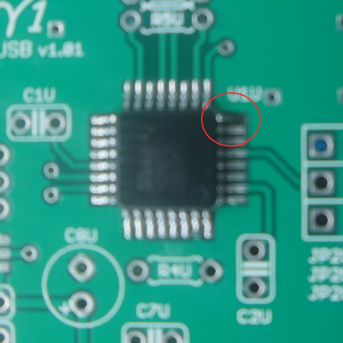
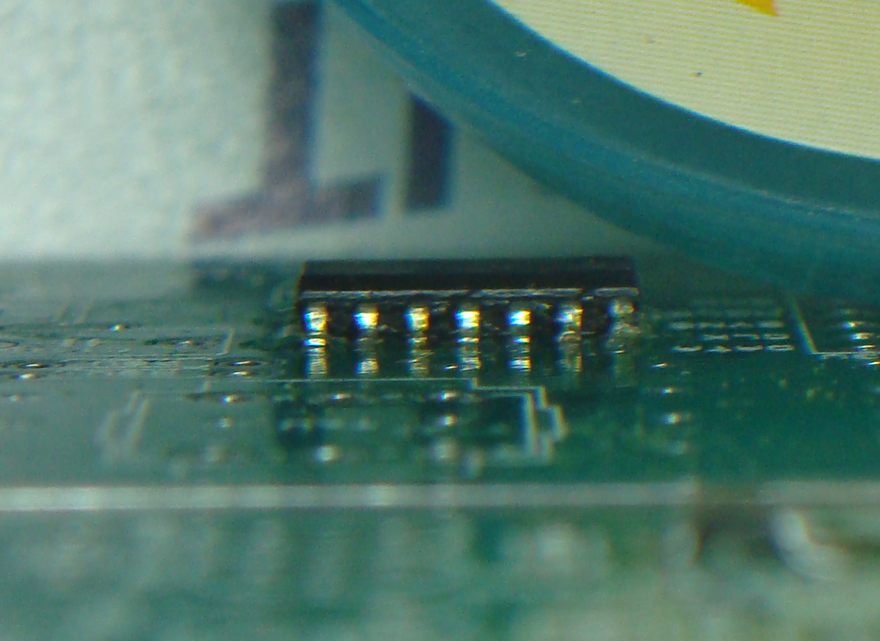
So based on TI's samples program I'm going to build and audition a y2 in the near to distant future. I see they don't allow for SN74AHC1G02DBVR and SN74AHC1G08DBVR. Could I substitute SN74AHC1G02DRLR and SN74AHC1G08DRLR, which are SOP-5 ICs instead of the SOT-23-5 ICs that are usually used in the y1.


A look at the datasheets would have revealed that the footprint dimensions are not compatible...
 
Dec 15, 2010 at 10:41 AM Post #1,487 of 1,546
Oops my bad. I guess it's time to start reading up on the data sheets, et al.
 
Dec 15, 2010 at 1:49 PM Post #1,488 of 1,546
i just resumed my unfinished y2 ++ as i am determined to finish it.i have been very busy at university so i couldnt continue it.
my y1 JP2D pin 2 and 3 dont read any ohm.i cleaned the board from any residues and it still doesnt read anything.same goes with one of the +5v on the dac board.
what shall i do?
 
Dec 17, 2010 at 5:55 PM Post #1,489 of 1,546

 
Quote:
my y1 JP2D pin 2 and 3 dont read any ohm.i cleaned the board from any residues and it still doesnt read anything.same goes with one of the +5v on the dac board.
what shall i do?

 
What does "any ohm" mean?
 
It doesn't make sense to measure resistance there unless you're checking for shorts to ground.  An "infinite" reading would be correct, or are you getting zero ohms (which is shorted)?  Also, make sure you take resistance measurements with the y1 powered off.
 
Dec 19, 2010 at 6:31 AM Post #1,490 of 1,546


Quote:


What does "any ohm" mean?
 
i am using manual multimeter.no matter what range i choose,the screen reading doesnt change from 1.i assume thats mean there is a short?
 
It doesn't make sense to measure resistance there unless you're checking for shorts to ground.  An "infinite" reading would be correct, or are you getting zero ohms (which is shorted)?  Also, make sure you take resistance measurements with the y1 powered off.
 
yes,i am checking for shorts(according to the initial check instructions).and i am not connecting the power supply while taking the readings.


Dec 19, 2010 at 7:27 AM Post #1,491 of 1,546


Quote:
 
 
i am using manual multimeter.no matter what range i choose,the screen reading doesnt change from 1.i assume thats mean there is a short?


No, on many meters "1" (with no decimal point or fractional digits) means "over-range", and when in resistance mode, it means "open circuit".
 
Dec 19, 2010 at 8:00 AM Post #1,492 of 1,546


Quote:
Quote:
 
 
i am using manual multimeter.no matter what range i choose,the screen reading doesnt change from 1.i assume thats mean there is a short?


No, on many meters "1" (with no decimal point or fractional digits) means "over-range", and when in resistance mode, it means "open circuit".


when i measure JP2D pin 1,it reads a few ohms as it should so that means its not shorted.and when it reads 1 on both pin 2 and 3,that also mean that it is not shorted?
 
Dec 19, 2010 at 4:22 PM Post #1,493 of 1,546


Quote:
 
when i measure JP2D pin 1,it reads a few ohms as it should so that means its not shorted.


No, that is not "as it should", if you're measuring resistance to ground.  "A few ohms" is a short.
 
Quote:
and when it reads 1 on both pin 2 and 3,that also mean that it is not shorted?

 
Correct.
 
Dec 19, 2010 at 5:00 PM Post #1,494 of 1,546
ok,i will try cleaning the back of the board again and check for any bridge and report back.
thank you for your assistance.always greatly appreciated.
 
Dec 24, 2010 at 2:48 PM Post #1,495 of 1,546
I just finished putting together my y1.  I plan on building the y2 in the near future, and the instructions say to not connect wires to the y1 board if its going to be mated to a y2.  However, on the "initial checks" page on amb's website, it seems the tests assume that the y1 has been connected with wires.  My question is, is it possible to perform the initial checks on my y1 without connecting the wires?
 
Dec 24, 2010 at 3:12 PM Post #1,496 of 1,546
You could just solder the connectors onto the Y2 board and plug it in.
Alternately you can test the DAC section of the Y1 by connecting an external power supply, jumper the USB board J2U pins 1 and 2 and then use either an optical or coax S/PDIF cable to connect the USB section to the DAC section.
 
Dec 28, 2010 at 7:56 AM Post #1,497 of 1,546
Values of R1U and R3U are 22 Ohm but I've measured the resistors I bought to Mouser and the DMM reads 68 Ohm . I don't know if this is such a low value that my cheap multimeter can't measure it accurately or Mouser sent me the wrong parts. Can I install these resistors anyways ? 
 
Dec 28, 2010 at 6:03 PM Post #1,498 of 1,546


Quote:
Values of R1U and R3U are 22 Ohm but I've measured the resistors I bought to Mouser and the DMM reads 68 Ohm . I don't know if this is such a low value that my cheap multimeter can't measure it accurately or Mouser sent me the wrong parts. Can I install these resistors anyways ? 


What are the resistor color bands?
 
Dec 29, 2010 at 7:16 AM Post #1,499 of 1,546
red-red-black-gold . I guess that this is the right color code for 22 Ohm. I don't know about the gold strip, maybe 1% tolerance? But what drives me nuts is that the DMM measures 68 or so ohms consistently. Ok. I've installed these resistors. Now the gamma 1 won't work unless I short JP2D 2-3. With JP2D 2-3 open I get:  4.5V -> 2.5V; 3.3V (dac and usb sections) -> 2.5V; 5V (the closest check point to the GND metal strip) -> 5V; 5V -> 2.5V. I have used the gamma2 board to set communication between the dac and usb sections. I made sure that pin headers in gamma2 and receptacles in gamma1 and vice-versa make contact with the DMM. So I guess that the problem lies in in U1D. I reflowed the chip but still I get the wrong voltages, so shorted JP2D 2-3  with U1D still installed and now voltages are right: 3.3V (both) -> 3.3V, 4.5V -> 4.7V, 5V (both) -> 4.9V. Power source is USB. I can hear music but volume out of my headphones connected straight to the 3.5mm out is too loud,even with the windows 7 audio mixer and the  music player's one (VLC) set to lowest volume. Also I can hear a lot of noise while the audio player is open but no music is playing, then I close the app and still I can hear some hiss, less than while the audio player is open but still quite  noticeable. I've used 470uF caps instead of 22uF for C24D and C25D, if that helps.
 
Dec 29, 2010 at 7:22 AM Post #1,500 of 1,546
Quote:
red-red-black-gold.


That's 22 ohms, 5%.  Btw, the resistors specified in the BOM are metal film 1% and should have 5 color bands.  Not that 1% accuracy is needed here, but what resistors are you using?  Those resistors are specified for their size and fitment.  I hope you didn't mount a bigger resistor tombstone-style.
 

Users who are viewing this thread

Back
Top