Watts Up...?
Nov 22, 2023 at 5:07 AM Post #4,366 of 4,668
Have you tried using different housing your devices to test out the RF rejection of various metals?

A solid block of aluminium is extremely effective at screening. And that's not the problem; it's electrical RF noise transmitted from input and output cables and the mains connection where the real issues lie.

@Rob Watts, I was wondering if your mojo2 DSP suite will be implemented in pricier full or tt models?

Given how well it was received - and how much work went into the DSP core - it's a no brainer for new designs. That said, it does take more FPGA overhead, and for other reasons new designs need bigger FPGAs.

Deary me!
You are being far far too polite.
Do these boxes come with real reptile-oil inside?

You always need some humility when it comes to subjective things - on two counts. Firstly I haven't heard them - and although technically I am highly dubious I can't rule out the possibility that something else is going on (perhaps RF isolation from ground inputs is included in the ground boxes?). Secondly, whenever we talk about results from listening, we have to be mighty cautious as it is very easy to get it wrong and prefer an aberration. Even though I have very careful objective listening tests and I think 99% of the time get it right - meaning I prefer a real objective improvement - there is always a possibility of error. One thing I do is repeated tests and reappraisals to make sure I am on the right track. Absolute certainty with subjective testing (no matter how objectively done) is an illusive thing.
 
Nov 22, 2023 at 6:44 AM Post #4,367 of 4,668
@Rob Watts I decided to experiment with upsampling 0.958652173913Hz using 100001 taps:

0.958652Hz with 16x Upsampling.png


So here the worst error is 0.017dB, which is smaller than in the previous test. I only upsampled one second of signal, so I haven't looked at the error variation across multiple cycles.

Anyway, the error is clearly worst as the signal crosses through 0, though here the error in general is larger than with the previous test, presumably because the highest signal component is at 22049Hz as opposed to 21KHz previously.

If I reduce the count of taps, the errors obviously get worse and the "buzz" around the zero crossing gets pretty severe:

0.958652Hz 16x 10001.png


Overall I can't see a problem with using a square wave like this to visualise the errors in upsampling, particularly as the signal crosses 0.
 
Nov 29, 2023 at 1:24 AM Post #4,368 of 4,668
A D/A Distortion Compensator ?

This mystery device -- TC17G005AF-0048 -- has been the subject of occasional discussion over the decades.
Since Rob Watts seems to seem to be informed about ASIC/FPGAs, I thought perhaps he could chime in.
Notably, certain Kenwood players in the late 1980s used a “TC17G005AF-0048.” 44-pin device.

=====
===== From a topical DIYA thread:

Kenwood DP-1100SG cd player which sounds great, no doubt helped by many items as standard eg twin Transformers, multiple regulators, separate digital / analog boards, cast alloy cdm, etc.
One thing it has is a ‘D/A Distortion Compensator’ chip, TC17G005AF-0048.
It sits between the digital filter, SM5804D, and the D/A chips, PCM56P-K, with an output feeding the I/V converter for nulling distortion at 1KHz -20dB and 100Hz 0dB.
It looks as though it may reclock the I2S lines.


=========

Any idea what it might be? Someone suggested a gate array. But at 44 pins, that’s quite a lot of processing for simple re-clocking.

ac98878e9fe6acc9b0f6fddc1b9cd6618f410f76.jpeg

5e4fc7e31bbc2872f6a855f04127037113856c6f.jpeg
 
Dec 1, 2023 at 8:42 PM Post #4,369 of 4,668
Except that square waves do not have transients, since they are composed entirely from fixed steady state sine waves. Putting a digital square wave into a perfect DAC will give the results of an ideal bandwidth limited square wave - which all of my DACs do with ease - at least within the constraints set by the WTA filter's >FS/2 stop band attenuation. The result of bandwidth limiting a square wave is reduced rise time plus Gibbs phenomena. You can read about it here.

Since it's a steady state signal, it won't suffer from reconstruction timing errors, as there are no transients in-between adjacent samples on the digital input.
Do you have lab graphs of any Chord DAC performance with square waves?

BTW: Back in 1993, Stereophile tested the Meitner IDAT.

The IDAT's reproduction of a 1kHz squarewave was unique: it doesn't suffer from time-domain distortions imposed by conventional digital filters. These distortions are seen as overshoot and ringing on the waveform. The IDAT's squarewave output, seen in fig.11, is virtually perfect, with no time-domain distortions. In fact, the squarewave looks as if it came directly from a signal generator, not a digital converter. It's difficult to overstate the achievement of designing a digital processor with such good time-domain performance.
https://www.stereophile.com/content/meitner-idat-da-processor-measurements
 
Dec 2, 2023 at 12:25 PM Post #4,370 of 4,668
Do you have lab graphs of any Chord DAC performance with square waves?

BTW: Back in 1993, Stereophile tested the Meitner IDAT.


https://www.stereophile.com/content/meitner-idat-da-processor-measurements
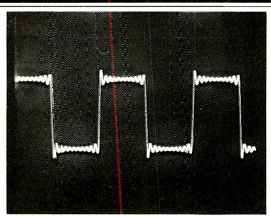
No because visibly they look exactly as they should look like. When you bandwidth limit a square wave it must have ringing on it - if it doesn't then the interpolation filter is a complete failure. If a DAC reproduces a square wave without ringing then it's time domain performance is an utter failure.
 
Dec 2, 2023 at 12:58 PM Post #4,371 of 4,668
No because visibly they look exactly as they should look like. When you bandwidth limit a square wave it must have ringing on it - if it doesn't then the interpolation filter is a complete failure. If a DAC reproduces a square wave without ringing then it's time domain performance is an utter failure.
Perhaps like this ???

audio_1987-12_technics_f8.jpg

Above from an Audio magazine metrics of a Technics SL-P1200 Compact Disc Player (Dec. 1987). Audio mag, while it was around, used to routinely publ. SW's in their full reviews.
 
Dec 3, 2023 at 5:11 AM Post #4,372 of 4,668
@Rob Watts In Stereophile's measurements for DAVE this graph:

1701597119218.png


from here:

https://www.stereophile.com/content/chord-electronics-dave-da-processor-measurements

shows frequency response curves for 44.1, 96, 192 and 384KHz. First of all, the graph is weird because the horizonal axis doesn't line up with the expected values, but we can ignore that for this question.

The 384KHz response has a different shape than the others. Instead of there being a knee in the curve followed by a sharp drop, this response appears to be like a conventional roll-off that a low pass analogue filter would give.

Is that the nature of this response?

I've been wondering whether this response is a result of bypassing the WTA 1 filter in DAVE. Shouldn't WTA 1 give a sharp drop for all input frequencies below 705.6KHz?
 
Dec 3, 2023 at 9:18 AM Post #4,373 of 4,668
@Rob Watts In Stereophile's measurements for DAVE this graph:

1701597119218.png

from here:

https://www.stereophile.com/content/chord-electronics-dave-da-processor-measurements

shows frequency response curves for 44.1, 96, 192 and 384KHz. First of all, the graph is weird because the horizonal axis doesn't line up with the expected values, but we can ignore that for this question.

The 384KHz response has a different shape than the others. Instead of there being a knee in the curve followed by a sharp drop, this response appears to be like a conventional roll-off that a low pass analogue filter would give.

Is that the nature of this response?

I've been wondering whether this response is a result of bypassing the WTA 1 filter in DAVE. Shouldn't WTA 1 give a sharp drop for all input frequencies below 705.6KHz?
Why not include the legend, instead of leaving readers to guess which colour trace is which?
 
Dec 3, 2023 at 3:29 PM Post #4,374 of 4,668
Why not include the legend, instead of leaving readers to guess which colour trace is which?
I included the link to the page so that a reader could find out directly if they were unsure what the graph is showing.

The curve that's different in its shape from the others is for the 384KHz sample rate, which is blue. Hence my question.
 
Dec 4, 2023 at 4:45 AM Post #4,375 of 4,668
Perhaps like this ???

audio_1987-12_technics_f8.jpg

Above from an Audio magazine metrics of a Technics SL-P1200 Compact Disc Player (Dec. 1987). Audio mag, while it was around, used to routinely publ. SW's in their full reviews.

Correct. although the ringing should be symmetrical, like this:

440px-Gibbs_phenomenon_10.svg.png

Image copied from Wikipedia article on Gibbs phenomena.

Above is a 4kHz square wave on an ideal DAC with 44.1kHz sample rate input.

@Rob Watts In Stereophile's measurements for DAVE this graph:

1701597119218.png

from here:

https://www.stereophile.com/content/chord-electronics-dave-da-processor-measurements

shows frequency response curves for 44.1, 96, 192 and 384KHz. First of all, the graph is weird because the horizonal axis doesn't line up with the expected values, but we can ignore that for this question.

The 384KHz response has a different shape than the others. Instead of there being a knee in the curve followed by a sharp drop, this response appears to be like a conventional roll-off that a low pass analogue filter would give.

Is that the nature of this response?

I've been wondering whether this response is a result of bypassing the WTA 1 filter in DAVE. Shouldn't WTA 1 give a sharp drop for all input frequencies below 705.6KHz?

Yes the Stereophile response curves are wrong - no way does it roll off at 18k at 44.1k. I assume that the AP was not configured to recognise the long latency for Dave.

As too the 384k response this is correct and there for all the sample rates - it would be visible if it was not curtailed by the WTA 1 response. It's a function of the subsequent digital filters (from 16FS to 104M) and the analogue filtering in the OP stage. These filters are fixed and functioning irrespective of the original input sample rate.
 
Dec 4, 2023 at 12:11 PM Post #4,376 of 4,668
As too the 384k response this is correct and there for all the sample rates - it would be visible if it was not curtailed by the WTA 1 response. It's a function of the subsequent digital filters (from 16FS to 104M) and the analogue filtering in the OP stage. These filters are fixed and functioning irrespective of the original input sample rate.
Did you choose to skip 2x upsampling for 8FS inputs on the basis it would do more harm than good?
 
Dec 5, 2023 at 9:10 AM Post #4,378 of 4,668
I am not sure I understand your comment - 8FS inputs are upsampled to 16FS in exactly the same way as 1FS with the WTA1 filter.
I thought when you said "function of the subsequent digital filters (from 16FS to 104M) and the analogue filtering in the OP stage" that you were explaining why the 8FS curve doesn't show the sharp drop caused by WTA 1.

The text says, "Only with 384kHz data (blue and green traces) does the ultrasonic rolloff continue smoothly, reaching –13.3dB at 190kHz." So the sharp drop caused by WTA 1 presumably comes at a higher frequency?

He doesn't allude to a smooth rolloff changing into a sharp drop - the drop would be expected at close to 192KHz. Instead the text can be seen as a mischaracterisation of the curve. Oh well.
 
Dec 5, 2023 at 10:56 PM Post #4,380 of 4,668
Mr Watts ... you've been hammerin' away at the albatross project -- WTA and gazillion-tap DF -- since the Deltec / DPA days
http://www.acoustica.org.uk/DPA/deltec.html
Have you considered releasing your designs for ASIC ? Maybe, to TI . AD or AKM.
FPGAs are nice as you can update firmware and make rapid prototyping changes. But in my experience -- industrial and manuf electronics -- it is hard to beat an ad hoc device (ASIC) for fast computation and performance.
Even w/o goin' ASIC, stuffing "lite" versions Chord d/a "processes" might be do-able with generic FPGA's.
Like ARM, Chord could become a viable non-fab "Holdings" company for WTA or other d/a "processes" .
 

Users who are viewing this thread

Back
Top