Warning About The Singlepower Extreme - Owners Please Read
Aug 10, 2009 at 12:22 AM Post #91 of 408
Quote:

Originally Posted by Spritzer
We aren't sure about that one, it really depends on what boards are in your actual unit. It would certainly be worth the time to open it up and take a few pictures.


Quote:

Originally Posted by kevin gilmore /img/forum/go_quote.gif
good idea

Do realize that the transformer cover will never fit on any of the replacment transformers,
and that extra holes in many of the chassis will be visible around the area of the transformer.


If icariums unit is any indication, sooner or later one of the transistors
inside is going to short out, then a couple of resistors toast. Since
its capacitively coupled output, no damage to the headphones will occur.
And hopefully the wall brick has a fuse inside.


Thanks for the help.

I've opened the wall brick and it looks fine, and there is a fuse soldered in place inside the wall brick - I'm having trouble reading the value of the fuse but it looks like a low amperage fuse. The transformer inside the wall brick is not secured in place and that is the source of the rattle that I complained about last year. I'm trying to decide the best way to glue the transformer down, so if I decide to transport it it wont flex the wires till they break. I think have some liquid nails around here somewhere.

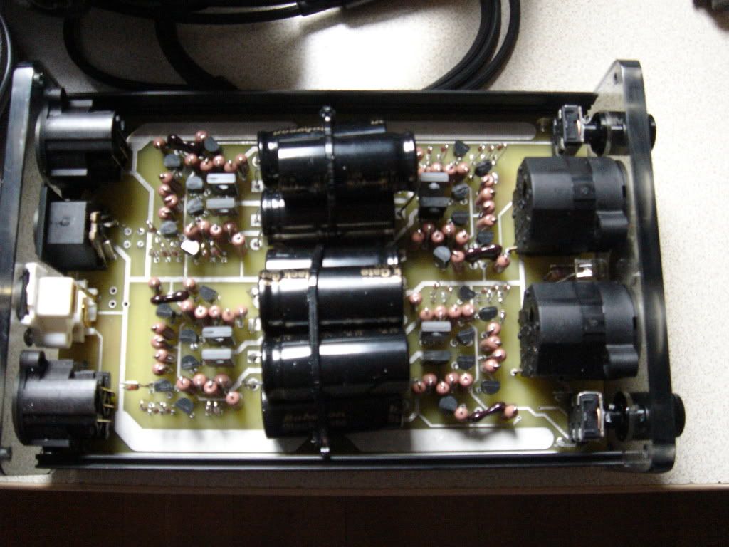
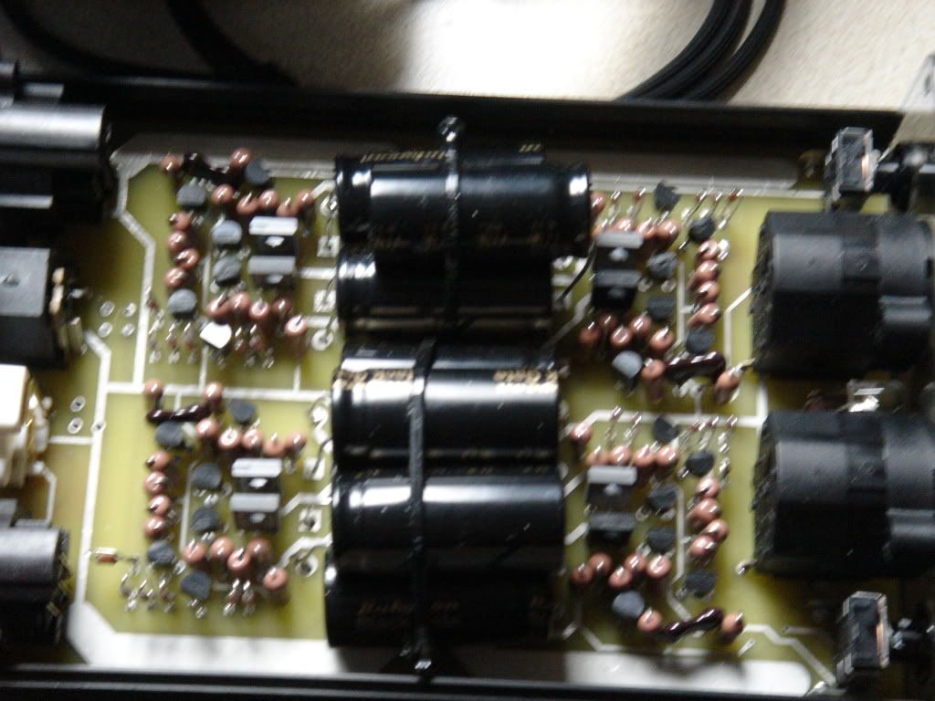
I will try to get the amp open soon and post some photos of that. The amp has been powered up 24/7 for the last 13 months and still sounds very good, while only running a bit warm but never hot. I wonder if Icarium's problem was due to the 4-6 stacked Sq Wave boards in close proximity with improper ventilation, or maybe due to the aweful power supply. Mine was built in 2008, with supposedly "upgraded parts" over the 2007 version, and blackgate caps.
 
Aug 10, 2009 at 12:56 AM Post #92 of 408
Quote:

Originally Posted by nurxhunter /img/forum/go_quote.gif
Much thanks, Nate, for all help to all. Right now, the EDCOR is the recommended replacement, as I understand. Based on some posts here and there, they make a nice sounding tranny.


I'm not sure this is a correct statement. There is an Edcor that would appear to be close to working but it's untested. It is certainly an attractive option because of it's price but no one has put one in an Extreme yet to see how it measures.

And thathertz, it's not worth discussing what would happen if the output weren't capacitor-coupled, there's no option for it not to be and all Extremes were built this way.
 
Aug 10, 2009 at 1:18 AM Post #93 of 408
Quote:

Originally Posted by thathertz /img/forum/go_quote.gif

Kevin, hypothetically, if it didn't have capacitively coupled output, what
would the typical damage be?

(sorry if I'm speaking OT)


Any DC output coupled amplifier is subject to destroying your load
(speakers, headphones) without proper protection. Tubes or solid
state, does not matter. Definitely includes items such as Futtermans
and Atmaspheres. (atmasphere uses fuses
frown.gif
)


(electrostat's are different and really don't care)

If you want a DC output coupled extreme, i did a thing called the bamaslama a while
back. Uses some sand to keep the output at zero volts, and requires twice as many
power supplys. Very few were built.
 
Aug 10, 2009 at 1:13 PM Post #94 of 408
Quote:

Originally Posted by n_maher /img/forum/go_quote.gif
Don't over-spec the trafo, there's no need. And before you contact Jack let me conduct a short private conversation with someone and we'll see about posting the specs that the replacement trafo should need so that you can save yourself (and Jack) a bunch of time.


Thanks for the help Nate. I had already sent off an inquiry to Jack based upon an email exchange with Kevin. I asked for a quote for 117v primary with 120v@.5A secondary and 6.3V@10A secondary. I look foward to your input.

Best,

Paul
 
Aug 10, 2009 at 1:52 PM Post #95 of 408
Quote:

Originally Posted by mourip /img/forum/go_quote.gif
Thanks for the help Nate. I had already sent off an inquiry to Jack based upon an email exchange with Kevin. I asked for a quote for 117v primary with 120v@.5A secondary and 6.3V@10A secondary. I look foward to your input.

Best,

Paul


Paul,

The issue here is that there are variations from amp to amp and I'm not sure there's a one-spec fits all solution. Your proposed specs will probably work but the rectified filament voltage may need adjusting via the dropper resistor or may just end up being a little on the low side. I wish there was a better answer but there isn't.
 
Aug 10, 2009 at 2:26 PM Post #96 of 408
Quote:

Originally Posted by n_maher /img/forum/go_quote.gif
Paul,

The issue here is that there are variations from amp to amp and I'm not sure there's a one-spec fits all solution. Your proposed specs will probably work but the rectified filament voltage may need adjusting via the dropper resistor or may just end up being a little on the low side. I wish there was a better answer but there isn't.


Thanks Nate. I did figure that given SP's "creative" approach to amp building I might end up needing to tweak a bit. My heater circuit has just one large capacitor after the rectifier. I guess some other amps have the tacked on extra capacitance and some a dropping resistor...
 
Aug 10, 2009 at 2:36 PM Post #97 of 408
Quote:

Originally Posted by mourip /img/forum/go_quote.gif
Thanks Nate. I did figure that given SP's "creative" approach to amp building I might end up needing to tweak a bit. My heater circuit has just one large capacitor after the rectifier. I guess some other amps have the tacked on extra capacitance and some a dropping resistor...


Yup, there's no one design for anything unfortunately. Thankfully the filaments don't care if you feed them exactly 6.3V.
 
Aug 10, 2009 at 3:33 PM Post #98 of 408
Here are 2 pictures of my singlepower squarewave XL. I don't know if it's exactly the same as Larry's. I have replaced the floorwart with a Sigma22. I would appreciate any input on whether it is safe.

DSC02839.jpg


DSC02842.jpg
 
Aug 10, 2009 at 9:03 PM Post #99 of 408
Nice packing job on that XL... I did not think mikhail could get that much in
a package that small. Sure looks exactly like the same parts as the unbalanced
version i have seen with the black gate output caps.
at least 2 of the resistors in there show changes indicating heat...
no change in circuit diagram either.


OK, real numbers from skylab's unit whose transformer is sinking slowly into the west.

transformer on for about 5 minutes. After that the voltage starts to sink.
With 117 VAC input...

DC filament voltage measured at the tubes 5.11 VDC
Plate voltage measured at the tubes 97 VDC
Cathode voltage at the tubes 47 VDC

My repaired unit with the electraprint transformer
DC filament 6.2 VDC
Plate voltage 149 VDC
Cathode voltage at the tubes 72 VDC

So its real easy to determine how much trouble your particular unit is in.
Just measure the filament voltage.
 
Aug 10, 2009 at 9:21 PM Post #100 of 408
Quote:

Originally Posted by kevin gilmore /img/forum/go_quote.gif
With 117 VAC input...

DC filament voltage measured at the tubes 5.11 VDC
Plate voltage measured at the tubes 97 VDC
Cathode voltage at the tubes 47 VDC

My repaired unit with the electraprint transformer
DC filament 6.2 VDC
Plate voltage 149 VDC
Cathode voltage at the tubes 72 VDC

So its real easy to determine how much trouble your particular unit is in.
Just measure the filament voltage.


Talk about sag...

Would you say that those new HV values are now appropriate for the circuit? Did you need to replace/adust any resistor values?

Thanks!
 
Aug 10, 2009 at 10:25 PM Post #101 of 408
Well that depends on whether or not you subscribe to the broksie version
for optimal bias of the output tubes. Clearly with 2 sections in parallel you
can go much higher. So a B+ of 180, and a current of 140ma with a cathode
of 500 ohms is going to give a lower output impedance of about 21 ohms
into a 32 ohm load.

B+ of 210 and a current of 190ma gives lower distortion...

And then its gonna really heat up the room.

and max power is a B+ of 230 and a current of 220 ma
For a grand total of 160 watts.
 
Aug 10, 2009 at 11:40 PM Post #102 of 408
Quote:

Originally Posted by kevin gilmore /img/forum/go_quote.gif
Nice packing job on that XL... I did not think mikhail could get that much in
a package that small. Sure looks exactly like the same parts as the unbalanced
version i have seen with the black gate output caps.
at least 2 of the resistors in there show changes indicating heat...
no change in circuit diagram either.


Hi. We appreciate your help and comments. Couple of questions:

Which resistors are showing signs of heat?

To increase the lifespan, do you think it would help to drill holes in the Sq Wave XL case (bottom, top or both)?

Is there damage that is guaranteed to happen over time no matter what because voltages or current is over the rating?

I am hoping to get my pictures done tonight.
 
Aug 10, 2009 at 11:47 PM Post #103 of 408
Quote:

Originally Posted by kevin gilmore /img/forum/go_quote.gif
Nice packing job on that XL... I did not think mikhail could get that much in
a package that small. Sure looks exactly like the same parts as the unbalanced
version i have seen with the black gate output caps.
at least 2 of the resistors in there show changes indicating heat...
no change in circuit diagram either.


Thank you Dr. Gilmore for your comments. I suppose if it doesn't kill me or my headphones I will probably stick with it until it craps out. I suppose turning it off will increase it's lifespan?

One thing about the damage is that initially when I got my sigma22, the voltage rails were accidentally the wrong way round. I realized this in seconds and unplugged everything. Perhaps the damage was caused then. Larry, yours might not exhibit the same damage.
 
Aug 10, 2009 at 11:52 PM Post #104 of 408
Quote:

Originally Posted by kevin gilmore /img/forum/go_quote.gif
Ok, this is clearly the hammond 266n12 transformer used in exactly
the same WRONG way as monoboy's unit.

Telltale signs
Black and White winding (110v)
Orange and Brown winding (110v)
Red and Blue winding (6.3v)
Grey and Yellow winding (6.3v)

mrarroyo's transformer is clearly one of the hammond 300 series
likely the 378x.

Telltale signs
Red, Violet, Red/yellow, red high voltage winding
yellow, yellow/black, yellow winding (5V not used)
green, green/yellow, green (6.3 VAC)
Brown, Brown/yellow, Blue/yellow, Blue (one of the 2 primary windings)
White, White/black, Black/red, Black (other primary winding)


So to recap I will install the 100K 1W resistor across the caps and open up the unit to verify the transformer I have.

If it is a 378x then I am ok, correct?
 
Aug 11, 2009 at 1:05 AM Post #105 of 408
Quote:

Originally Posted by mrarroyo /img/forum/go_quote.gif
So to recap I will install the 100K 1W resistor across the caps and open up the unit to verify the transformer I have.

If it is a 378x then I am ok, correct?


If it is a 378x then you are fine. Would probably go 150K 1 Watt just
in case the voltage is a bit high.
 

Users who are viewing this thread

Back
Top