USB Powered Pimeta
Dec 1, 2008 at 10:10 AM Thread Starter Post #1 of 36

rds

Headphoneus Supremus
Joined
May 4, 2008
Posts
2,045
Likes
31
I'm planning to build a pimeta with tread that can be optionally powered by usb. When wall powered it will have 24V ac coming in to the tread.

I will be using lmh6321 buffers and ad8610/20 op-amps.

It seems I could bypass the tread and power the pimeta directly with usb as both the lmh6321 and ad8610/20 are rated down to 5V.

Alternatively I go use a dc-dc converter to get 9v or more (and even run it through the tread).

I'd love it if some of our local experts could weigh in on what seems like the better method.

FYI, I will have a bantam DAC in there too. The idea is to have a DAC/amp I can plug directly into my laptop without an adapter if I don't have room to carry one. Also I don't want to deal with batteries, so that's out.
 
Dec 1, 2008 at 10:28 AM Post #2 of 36
Quote:

Originally Posted by rds /img/forum/go_quote.gif
It seems I could bypass the tread and power the pimeta directly with usb as both the lmh6321 and ad8610/20 are rated down to 5V.


How do you plan to get +/-5v from the usb line?
 
Dec 1, 2008 at 10:43 AM Post #3 of 36
I don't think you'll be terribly happy with those chips on 5V, AD8610 is rated to +/-5V, not 5V, but in that amp I've seen it run lower voltages, but it swings 1.2V away from rails so your voltage swing won't be very large on 5V.

DC-DC booster would work but they're generally noisy and you would need to clean them up (possibly another regulator).

Also note that USB 2.0 will not output over 500mA of current and boost converters have some serious overhead. LMH6321 draw 15mA each, AD8620/AD8610 are only 3.5mA per amplifier. That adds up to about 55mA draw on the Pimeta and judging by that converter you linked, it would barely keep 60% efficiency so likely 100mA drawn off the USB line.

JamesL :
1) Pimeta runs on a single supply (don't need +/-5, just 5V).
2) The booster he linked allows for dual supply voltage.
 
Dec 1, 2008 at 10:52 AM Post #4 of 36
Quote:

Originally Posted by FallenAngel /img/forum/go_quote.gif
JamesL :
1) Pimeta runs on a single supply (don't need +/-5, just 5V).
2) The booster he linked allows for dual supply voltage.


eh yeah.. that's what I meant.
5V to the pimeta will only supply bout +/-2v to the opamp supply pins. =/
Also, the pimeta has pads to allow for a dual supply.
 
Dec 1, 2008 at 11:13 AM Post #5 of 36
Thanks guys.
FallenAngel - that's just the kind of facts I was looking for.
I'm think that the best solution might be to use the converter and run it through the tread. I could use the NDTS0515C, which supplies 15V and have the tread regulating like 14V or so.
That would mean I should a 12V ac wall wart rather than 24, but overall seems like a good solution.
Obviously I'd have a dpdt to switch between usb and wall power.
What do you think?
 
Dec 1, 2008 at 11:45 AM Post #7 of 36
Quote:

Charge pumps will get you a negative rail, but you still have to worry about your current draw, noise and the fact that the rail droops under load.


I don't need a negative supply, but thanks.
Current draw seems OK for the configuration mentioned in my last post.
Noise is an issue. I will be tread regulating but further circuit ideas would be great.
I think regulation should alleviate the V drop. The problem would be if the voltage supply drops below what I'm trying to regulate. So I would probably want to regulate my 15V supply to 13V. ...not totally sure about that one.
 
Dec 1, 2008 at 12:02 PM Post #8 of 36
Quote:

Originally Posted by JamesL /img/forum/go_quote.gif
eh yeah.. that's what I meant.
5V to the pimeta will only supply bout +/-2v to the opamp supply pins. =/
Also, the pimeta has pads to allow for a dual supply.


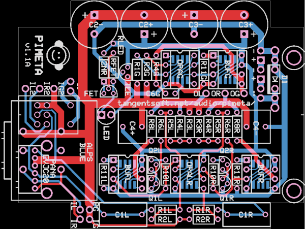
pimeta-1.1a-hires.png

Where?

NDTS0515C costs $17 and draws up to 757mA, might not be the best.

Maybe use an LDO regulator and don't have too much capacitance on the Pimeta to keep it happy. Won't drop much and you get as much voltage as possible.
 
Dec 1, 2008 at 12:25 PM Post #10 of 36
Try the TI DCP02 series. They're kinda pricey, but easy to use and available in useful values like +/- 15V (or wired for +30V) in a single package (DCP020515D). I have used this chip for a USB powered cmoy in a similar sort of configuration and it works well. Regulation is very poor though (obviously, as it's unregulated), and they are indeed a little noisy.

These chips run at 800KHz, I would recommend an LC filter before a LDO reg with good ripple rejection, LM317 is quite terrible at rejecting high frequency noise, so at the very least add some L to the switcher's output before piping it into the TREAD.
 
Dec 1, 2008 at 12:51 PM Post #11 of 36
Quote:

...I would recommend an LC filter before a LDO reg with good ripple rejection...


Are you suggesting an LC -->LDO-->Tread? I was thinking LC-->tread. Keep in mind that it will be going through the bridge rectifier after the LC, and then the Tread filter cap.
Seems like that might be good enough...

Thanks for the info on the TI chip - that looks great.

EDIT maybe the LDO is a good idea. But I think trying to get 30V out of the usb with the dc/dc is pushing it - a lot (current limits). Just using Vout 1 for 15V should be fine.
So I would need an LDO to regulate 15V. Any suggestions?
 
Dec 1, 2008 at 1:25 PM Post #12 of 36
You seem to be trying to feed the TREAD with the USB power or the wall power.

Why don't you think about it as if you are feeding the Pimeta board either TREAD power or USB power? It would seem to be a simpler way of logically arranging it. You have a TREAD board providing X voltage or a USB board providing Y voltage. Yes, it may be a little bit larger, but it seems like it would clean up the logic and design a bit. You could then use a diode OR to chose which actually provides power to the Pimeta. This is like the tomb Pimeta trickle charges (just replacing the batteries with your USB board)
 
Dec 1, 2008 at 2:13 PM Post #13 of 36
Quote:

Originally Posted by rds /img/forum/go_quote.gif
Are you suggesting an LC -->LDO-->Tread? I was thinking LC-->tread. Keep in mind that it will be going through the bridge rectifier after the LC, and then the Tread filter cap.
Seems like that might be good enough...


Through the bridge rectifier ?
confused_face(1).gif
Why would you pass DC through the bridge rectifier and loose 0.7V for nothing ?

A tread seems anyway a bad idea to me. You are boosting voltage and then burn 3V of hard earned voltage. A potentially interesting LDO is the TL750L10CLP familly from TI. You have TO92 packages (easy to work with) an a low dropout at highish voltage (8V or 10V)

Another thing might be to make use of the strong PSRR of the opamps at low frequencies to only use a capacitance multiplier. It would be effective to reject high frequency noises (to which opamps are very sensible) and would not drop too much voltage (if you're not trying to reject ripple at low frequencies)
 
Dec 2, 2008 at 1:28 AM Post #14 of 36
OK, this is great advice guys.

Now I think I have a good potential power system.

Here's the plan:
DCP020515DP (15V out) ---> (1uF and 0.1uF cermanic caps) --->PLY10AN1121R8R2 ---> TL750L12CLP ---> Pimeta.
Now I think I was pretty clever to pick the PLY10AN1121R8R2 - if you look at the first graph in the datasheet you'll see it has a peak common mode loss at about 800kHz. That is the switching frequency of the DCP020515DP.
What do you think?
[By the way after the ldo reg I'm looking at 12V]

EDIT - I know you guys hate wasting power so I'll mention that the dc-dc converter has a minimum output of 14.25V and the LDO has a minimum requirement of 13V.
 

Users who are viewing this thread

Back
Top