Topaz Low-Capacitance Isolation Transformers - for Affordably Clean Power
May 23, 2019 at 10:12 AM Post #271 of 568
Good morniing all :)

Upon reading back on the first page it was recommended to use a single receptacle for all components and to keep cord length and outlet spacing to very minimal for low impedence and leakage currents.

Does leakage currents basically represent the current flow across the electrical circuitry that goes beyond what is usable and what is actually needed for your components? Basically, leakage currents = wasted current/extra unncessary noise? I'm now thinking of a better way to setup my rig. NOT using my Art4x4pro power distributor and plugging my LPS that powers my dac straight into the PLC Puck, along with my headphone amp plugged into the second receptable of the Puck.

Wall outlet > APC volt regulator > ISO > (Using only 1 receptacle on ISO) Blue Circle PLC Puck (x2 receptacles) > Puck Receptacle#1: DAC / Receptacle#2: Headphone amp

Since it was stated that it's best not to have power conditioners (although the PLC Puck being one) the art4x4pro has an LED on/off switch, 6ft' power cable and surge protection. Basically it checks all of the marks on that list. I'm going to try this setup when I get home and test for SQ.

My other concern is the LPS that powers the Paul Pang v2 usb card... Now because this LPS connects to the usb card connected to the computer which will all know harbors tons of noise due to the SMPS, would it be best to keep this LPS on an entirely different circuit? If I were to keep this LPS connected to the ISO would the noise generated from the PC not transfer back to the ISO and into the headphone/dac?

Just for reference my PC is connected to another wall outlet in my room like so:

Wall outlet > APC UPS > x6 receptacle power conditioner > Both of my monitors (powered by smps wall warts), PC, and audio interface (Behringer UMC404HD) are connected to this power conditioner, along with the LPS that powers the PPA V2

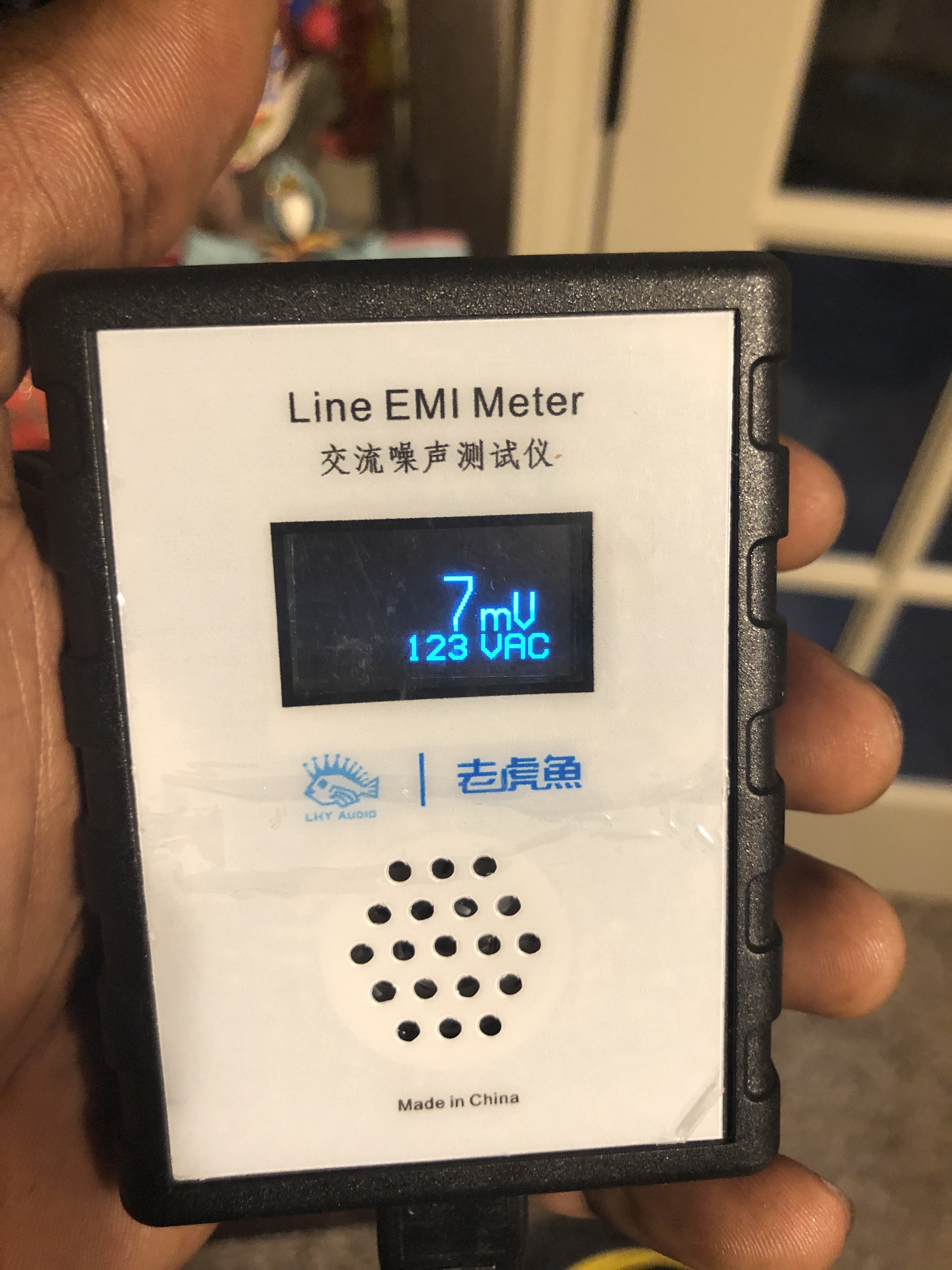
Btw as a note I wanted to mention that the detail extraction and noise floor was lowered to a level I'm still trying to comprehend. The decay as mentioned and extension of micro details is much more present and noticeable. Now it's just a matter of keeping things connected where they can yield optimal performance.

Anthony
 
May 23, 2019 at 12:17 PM Post #272 of 568
Does leakage currents basically represent the current flow across the electrical circuitry that goes beyond what is usable and what is actually needed for your components? Basically, leakage currents = wasted current/extra unncessary noise?
Not quite, they're current loops that form between electrically connected devices.

See post 25 here
https://audiophilestyle.com/forums/...-of-ac-mains-isolation-transformers/#comments

I'm now thinking of a better way to setup my rig. NOT using my Art4x4pro power distributor and plugging my LPS that powers my dac straight into the PLC Puck, along with my headphone amp plugged into the second receptable of the Puck.

Wall outlet > APC volt regulator > ISO > (Using only 1 receptacle on ISO) Blue Circle PLC Puck (x2 receptacles) > Puck Receptacle#1: DAC / Receptacle#2: Headphone amp

Since it was stated that it's best not to have power conditioners (although the PLC Puck being one) the art4x4pro has an LED on/off switch, 6ft' power cable and surge protection. Basically it checks all of the marks on that list. I'm going to try this setup when I get home and test for SQ.
Im not sure what the puck does or if it would be beneficial after the topaz, you want filterless power distribution after the topaz, the simplest being a tripp lite power strip with no movs or anything just wire connecting the receptacles.

My other concern is the LPS that powers the Paul Pang v2 usb card... Now because this LPS connects to the usb card connected to the computer which will all know harbors tons of noise due to the SMPS, would it be best to keep this LPS on an entirely different circuit? If I were to keep this LPS connected to the ISO would the noise generated from the PC not transfer back to the ISO and into the headphone/dac?
The power supply for the usb card should not be on the topaz. a normal power supply for the iso regen should be on the topaz, however, if using an uptone ultracap, the charging supply should not be on the topaz.
 
May 23, 2019 at 5:09 PM Post #273 of 568
@Zenvota The blue circle plc puck is a power line filter. The double outlet plugs into a single receptacle.
plcpuck.jpg

852460-blue-circle-audio-plc-puck-2-outlet-power-conditioner.jpg


I think ill remove the puck and place it to connect my PC, see how it sounds.
 
May 24, 2019 at 7:45 PM Post #274 of 568
Hello everyone. I just bought and received an Ultra Isolator myself. Am I wrong or is it already wired for balanced power? It looks odd in both the configuration and using both brown and red wiring jackets which from what I know usually are both used for hot wires? I'm not really educated enough in this matter to know what's going on here and there's not really a detailed wiring configuration like one sees on other models, only a single picture on the side that I've included.

I purchased this one as it was essentially brand new (unused), and it had an actual inlet that one could use with a power cable of one's choosing (which I thought would be easier than the usual user wired models) but instead of it being a 20 amp iec or even a 5-20p inlet plug it's a 6-20r inlet plug, so that has to be replaced with either an iec inlet or hard wiring a nice power cable into it (the outlet will be replaced with a better one as well). There is an included power cable with hospital grade plugs, and I could just swap the female plug end onto a nice power cable (if the hot and neutral wires are reversed on 6-20r plugs compared to standard 20 amp plugs since the horizontal and vertical pins are reversed though that would be something I need to know ahead of time, again I'm not educated enough on that matter), but I think I may want nicer wiring inside the unit anyway and I want to replace the outlets on the unit as well, so why not just go the whole way. I'm just intrigued by the wiring configuration.

I apologize for the last picture being blurry. Any help is greatly appreciated, thank you.

DSC06471.jpg

DSC06472.jpg

DSC06473.jpg

DSC06474.jpg

DSC06475.jpg
 
May 31, 2019 at 10:16 AM Post #275 of 568
Bump for MasterSplinter's concern.

Out of curiosity, does anyone have experience 'upgrading' the receptacles of these topaz transformers with something like an Oyaide, Synergistic Research or Furutech? Any audible benefits? I'm not able to change receptacles in my current room so it has me thinking that perhaps swapping the topaz receptacle would yield some audio bliss! Plus it will add some extra flare and color to it. Mine is in plain sight so it would be nice to look at as well.
 
Jun 1, 2019 at 12:33 AM Post #276 of 568
@MasterSplinter
I’m not sure of the wiring for your units since it’s typical for the -31 and and -32 that I’ve seen.

@bequietjk
Let us know what you find. I was going to swap the receptacles on my aluminum enclosure unit with some rhodium ones but the deal fell through so now I only have 2 of the 8 I was planning on having. Those two are now in the walls instead.
 
Jun 1, 2019 at 2:17 AM Post #277 of 568
@oneguy I'll have to crack open the panel to see how difficult it will be replacing the receptacle. I've never done something like this and A) do not want to fry myself and B) fry the unit. But I'm looking towards either the Maestro or the Oyaide R1 receptacle!
 
Jun 1, 2019 at 5:36 AM Post #278 of 568
Replacing the receptacles is straight forward so you shouldn’t have any problems. You can and should check for grounding to the case on the hot and neutral of the primary and secondary before plugging it in just to make sure you won’t get electrocuted.
 
Jun 1, 2019 at 3:38 PM Post #279 of 568
You can and should check for grounding to the case on the hot and neutral of the primary and secondary before plugging it in just to make sure you won’t get electrocuted.
Could you elaborate on this?

When I tested my transformers with a floating neutral secondary(the way the prewired, -12 -22 -32, units are stock), I measured ~120 from hot to neutral, but hot or neutral to ground read nothing. I measured 120 from either hot/neutral to ground at the wall outlet, and confirmed continuity of the ground from the wall to the transformers output.
 
Jun 1, 2019 at 4:21 PM Post #280 of 568
Could you elaborate on this?

When I tested my transformers with a floating neutral secondary(the way the prewired, -12 -22 -32, units are stock), I measured ~120 from hot to neutral, but hot or neutral to ground read nothing. I measured 120 from either hot/neutral to ground at the wall outlet, and confirmed continuity of the ground from the wall to the transformers output.

I test mine by measuring resistance from the case to primary-hot, primary-neutral, secondary-hot and secondary-neutral. All of these should read as on open circuit. If their open circuits no voltage is flowing between the two and no risk of shock.

ADD: Case to ground should read as a closed circuit to shunt any current flow in the event you do get a short from one of the wires.
 
Last edited:
Jun 1, 2019 at 5:29 PM Post #281 of 568
I test mine by measuring resistance from the case to primary-hot, primary-neutral, secondary-hot and secondary-neutral. All of these should read as on open circuit. If their open circuits no voltage is flowing between the two and no risk of shock.

ADD: Case to ground should read as a closed circuit to shunt any current flow in the event you do get a short from one of the wires.

Do you have secondary neutral grounded?
 
Jun 1, 2019 at 7:11 PM Post #282 of 568
Do you have secondary neutral grounded?

I don’t. My three larger transformers are -32’s so they aren’t wired that way and my 2 smaller ones are -31 but only 125va so I haven’t had a use for the them yet.
 
Last edited:
Jun 1, 2019 at 8:00 PM Post #283 of 568
I don’t. My three larger transformers are -32’s so they aren’t wired that way and my 2 smaller ones are -31 but only 125va so I haven’t had a use for the them yet.

Hmm, so if I measure resistance(the ohm symbol at 2m) and put the probes together I get .000, ground to case(the center unpainted iron part?) I get .000, but the secondary hot or neutral to case or ground I get no reading.
 
Last edited:
Jun 1, 2019 at 8:37 PM Post #284 of 568
It seems my unit doesn't even turn on with a 250 volt 6-20r to 120 volt 5-20p adapter cable (cost nearly $50 to find that out :frowning2: 
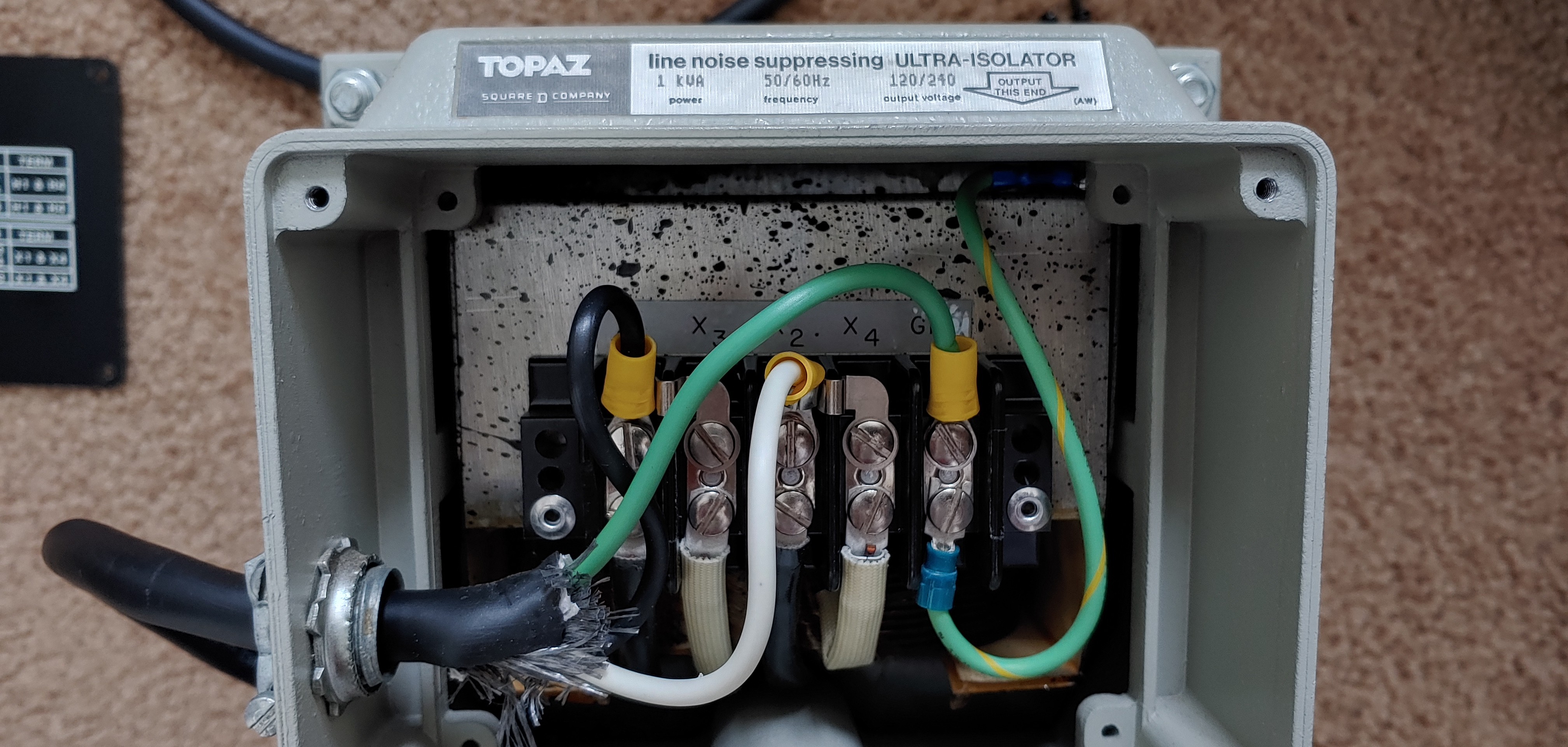
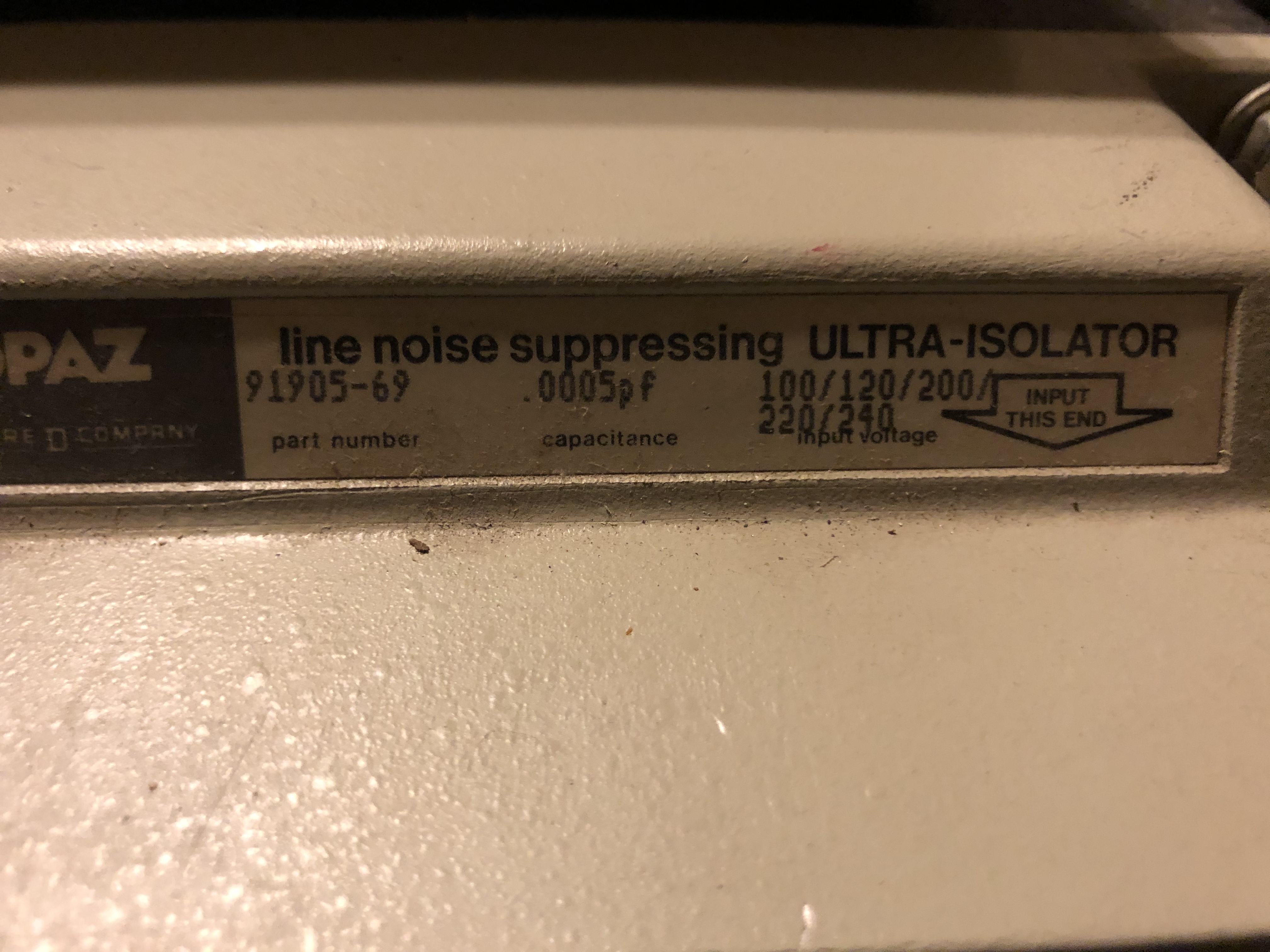
). I thought these were nearly all step up step down 120/240 in and out units (all the ones I've seen have been specified as such and this unit is brand new unused), so I expected this to work, but maybe it has to be one voltage all the way from input receptacle to compatible cable? I could try just wiring in a standard iec, but I'm wary of spending more, so I'd have to test it with a cheaper one and the wiring to match (lugs only on one end). I may try just stripping a disposable power cable and hard wiring it in to see if that works.

I actually accidentally purchased this unit as I thought the input inlet plug was a 5-20 one, but got the pins mixed up (it's not something I'm used to looking at, so I didn't expect the reverse to exist). So I'm trying to see if this now nearly $350 mistake can actually work out for me.

I did find out the wiring uses a floating neutral, which I had no experience with (just putting standard 15 or 20 amp plugs on power cables and putting in some wall outlets). There's just no information out there at all on this unit and it'd figure if I grabbed the only one that isn't both 120 and 240 volt compatible.
 
Last edited:
Jun 1, 2019 at 8:54 PM Post #285 of 568
I thought these were nearly all step up step down 120/240 in and out units (all the ones I've seen have been specified as such and this unit is brand new unused
The hardwired ones will specifically say 120/240 on both the input and output and have a plate with thr wiring diagram:
923853525_o.jpg Topaz_Jumpers.jpg

The prewired ones are often one voltage in and one out
s-l1000.jpg
 

Users who are viewing this thread

Back
Top