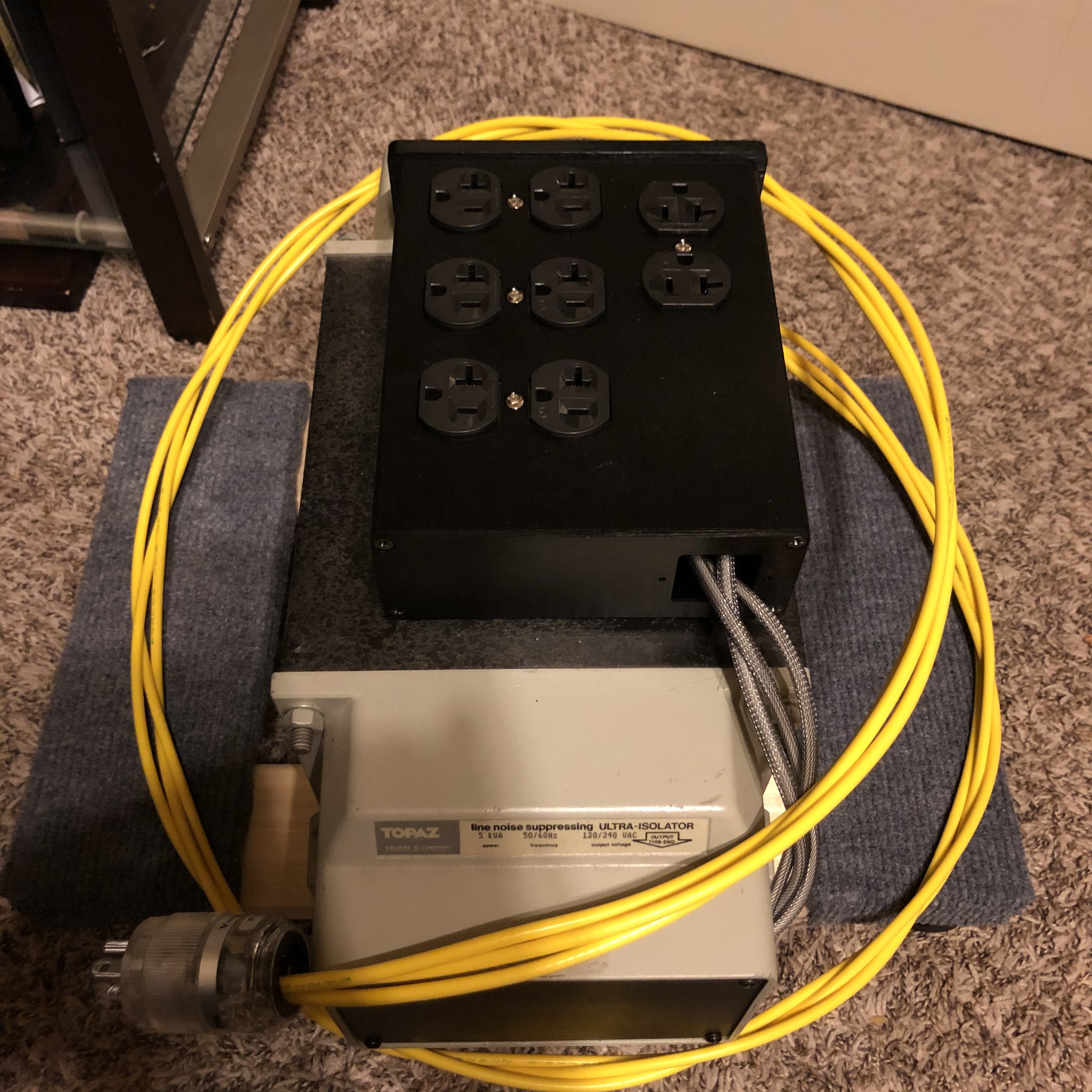
Finally receiving the 2.4kVA Topaz, here is a list of inspections and tests for 'older' transformers.
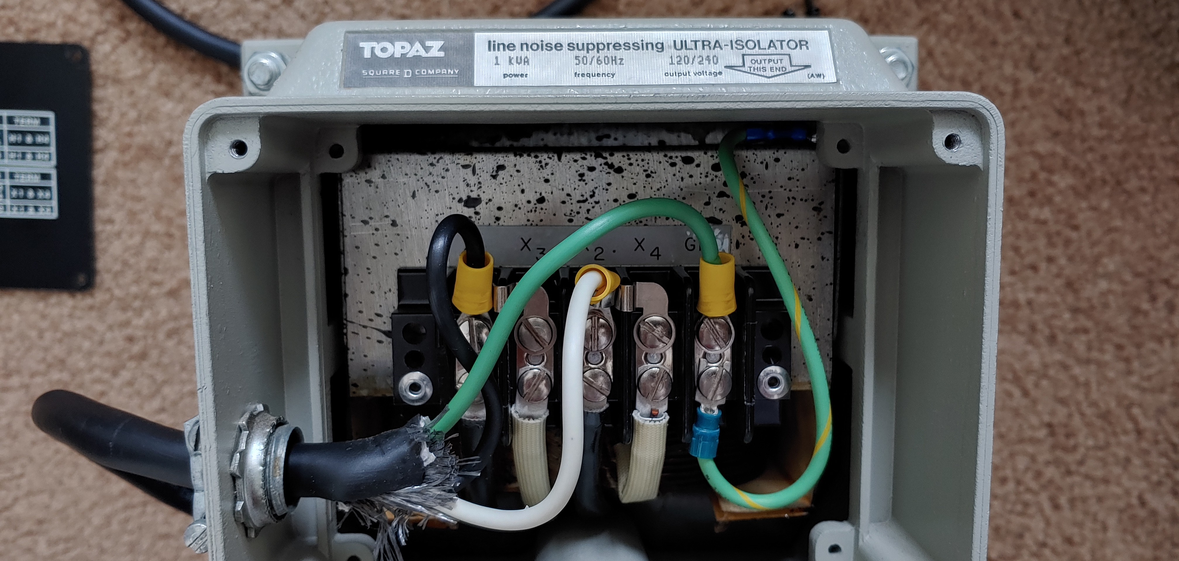
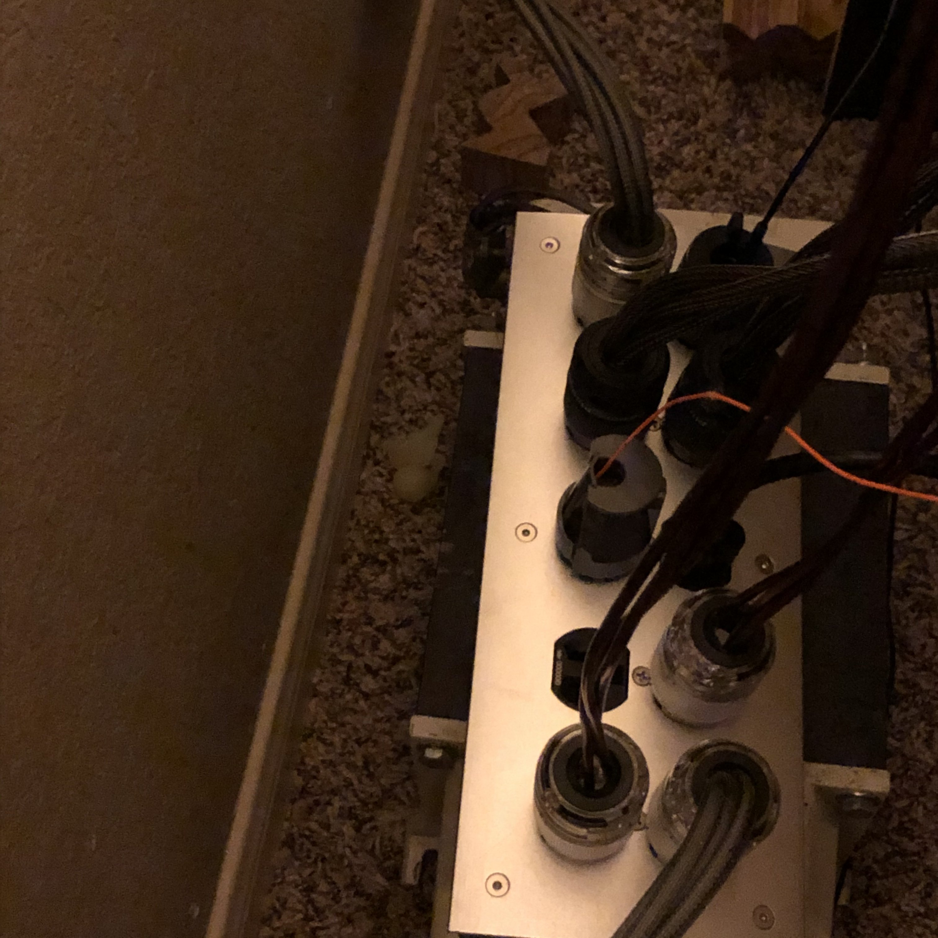
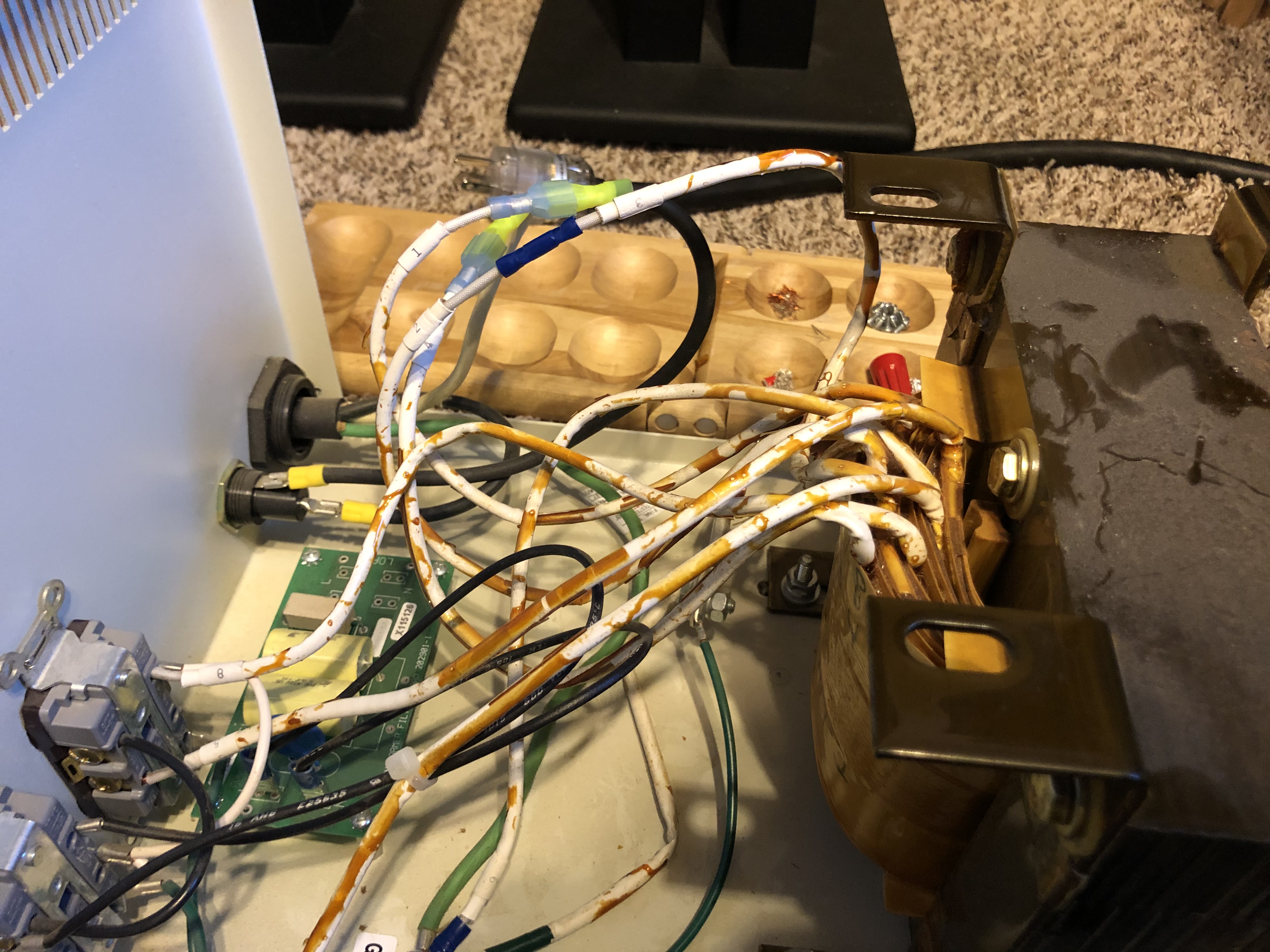
With the AC power totally unplugged from the Transformer, open both ends of the terminal boxes.
1. Look for debris, gunk dirt, especially on the terminals. A quick spray with Electra-Clean, or Iso-Propyl, with a clean rag and remove any contaminants. Don't go overboard with the spray, since the chemicals may dissolve any labels.
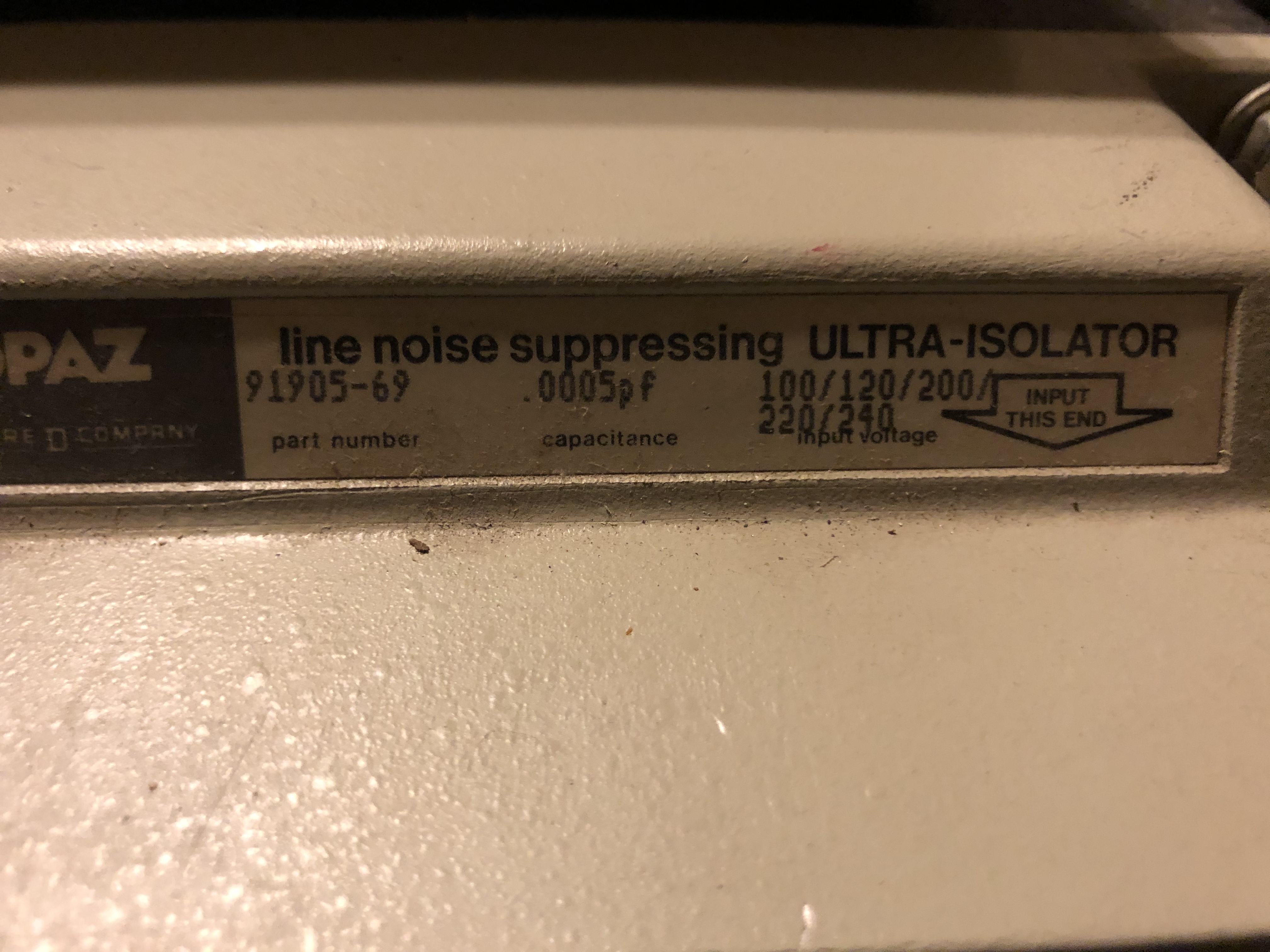
2. Check the connections, make sure the are tight, but not FT. The earth/ground connection is very important. This 2kVA had the shield wired to the incoming neutral which was rather odd, it should be on the earth chassis connection. Compare the voltage you are to use with the Topaz Bulletin 05160-001-TI REV A August 1984. I removed it to measure what was on it, close to 1/2 line volts on the primary.
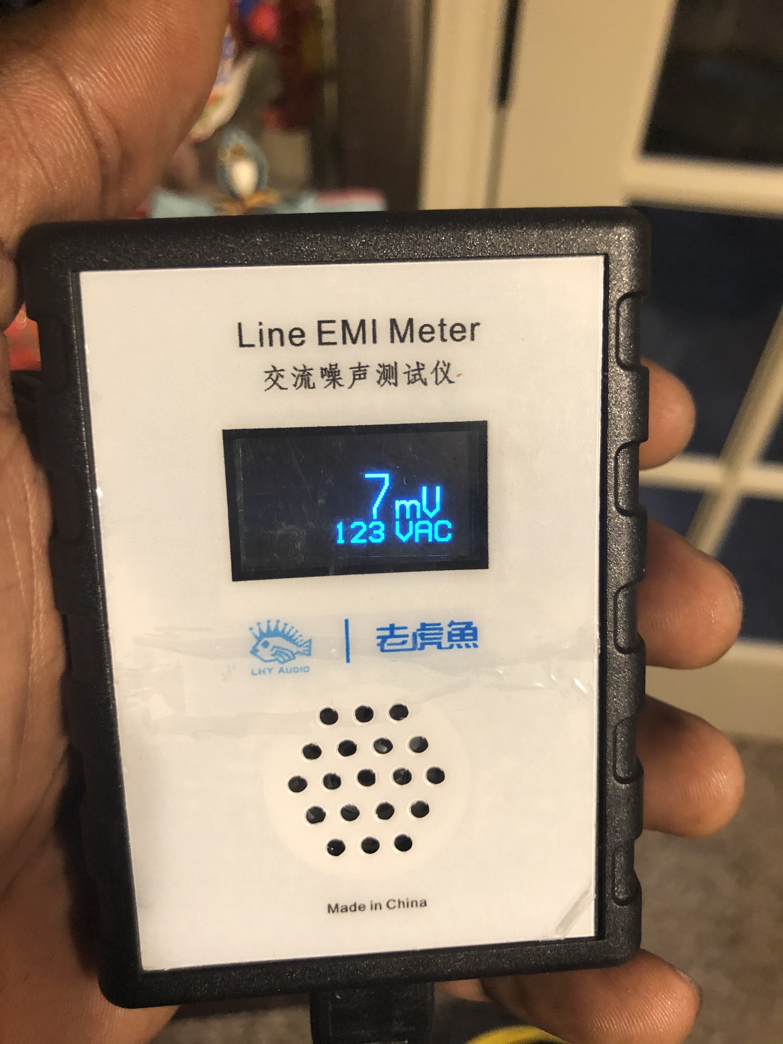
3. Obtain an Insulation Resistance (IR) Meter. An IR meter applies a DC voltage on the transformer to measure its insualtion resistance. The voltage applied needs to be 2 x the working voltage on the transformer. For 120V systems, use 250V, for 230V systems use 500V. Since the IR meter is DC, it will not jump to the secondary from the primary or vice versa. The one I use is
here. There are many others.
Connect the red lead to H1 and black lead to earth/ground.
Keep the meter in test mode on for at least 30s and observe the readings.
The minimum is 1000 M Ohm. The 2.4 kVA delivered Topaz had a reading of 2457 M Ohms - Brilliant!
Disconnect the Red lead from H1 and connect to X1, leave the black connected.
Keep the meter in test mode on for at least 30s and observe the readings. The minimum again is 1M Ohm, with the same voltages applied as before.
If all IR readings are good, then, there's good confidence to apply power, but not yet.
4. Prepare the connections to the line and the load, make sure that the connectors on plugs if you use them are all good and the connected right way round. Leave the connections off the transformer for now.
Use the IR meter to test the cable, same levels for voltages apply.
This time connect the red lead of the IR meter to the hot conductor (Black for USA/Canada, Brown for IEC) and the earth/ground cable. Ensure that any ends don't touch metals. Start the test, it should show open, or OL. If less than 1M Ohm, check the connections again. If it's an old cable, it may have to be retired as a lot of moisture contributes to a low reading.
Repeat the test for the white cable (USA/Canada, Blue for IEC), and compare with the hot.
There's then no shorts in the connecting cables, so now they can be connected to the transformer terminals.
5. With any multi meter, connect the leads to the output of the transformer to X1 and X4. I used a small Variac to gradually wind up the voltage, but this is luxury. Power on the primary of the transformer and you should see 120V or 230V depending on which config you have.
6. Leave the transformer on no load for a 'while' at least 3-6 hours, to listen for buzzes and measure the case temperature. Use your hand to gauge the temperature, the 2kVA was barely warm, and you could just hear a very faint hum with an ear about 3" from the frame.
7. If that's all good, the transformer is ready for use.
A) IR testing is at elevated voltages. Touching any terminals or probes while the IR test is on, WILL give you a very nasty bite. After the test, allow a few seconds for the voltage to discharge through the IR meter. The IR meter will let you know if any residual voltage is left.
B) 120V or 230V live testing requires the correct PPE, glasses and gloves. These voltages will and can kill. If you are not comfortable working on systems like this don't. Seek a professional out, these tests don't take long and the meters are in every electrician's kit.


![0227211105_HDR[1].jpg](https://cdn.head-fi.org/a/11441897.jpg)


")
