@londere
I don't have the ak4499 model, so this can the wrong, but based on what I see in this randomly googled photo, I think this ak4499 model opamps voltage is +-7V.:
https://twitter.com/mustdidreamer/status/1325093638796271616/photo/1
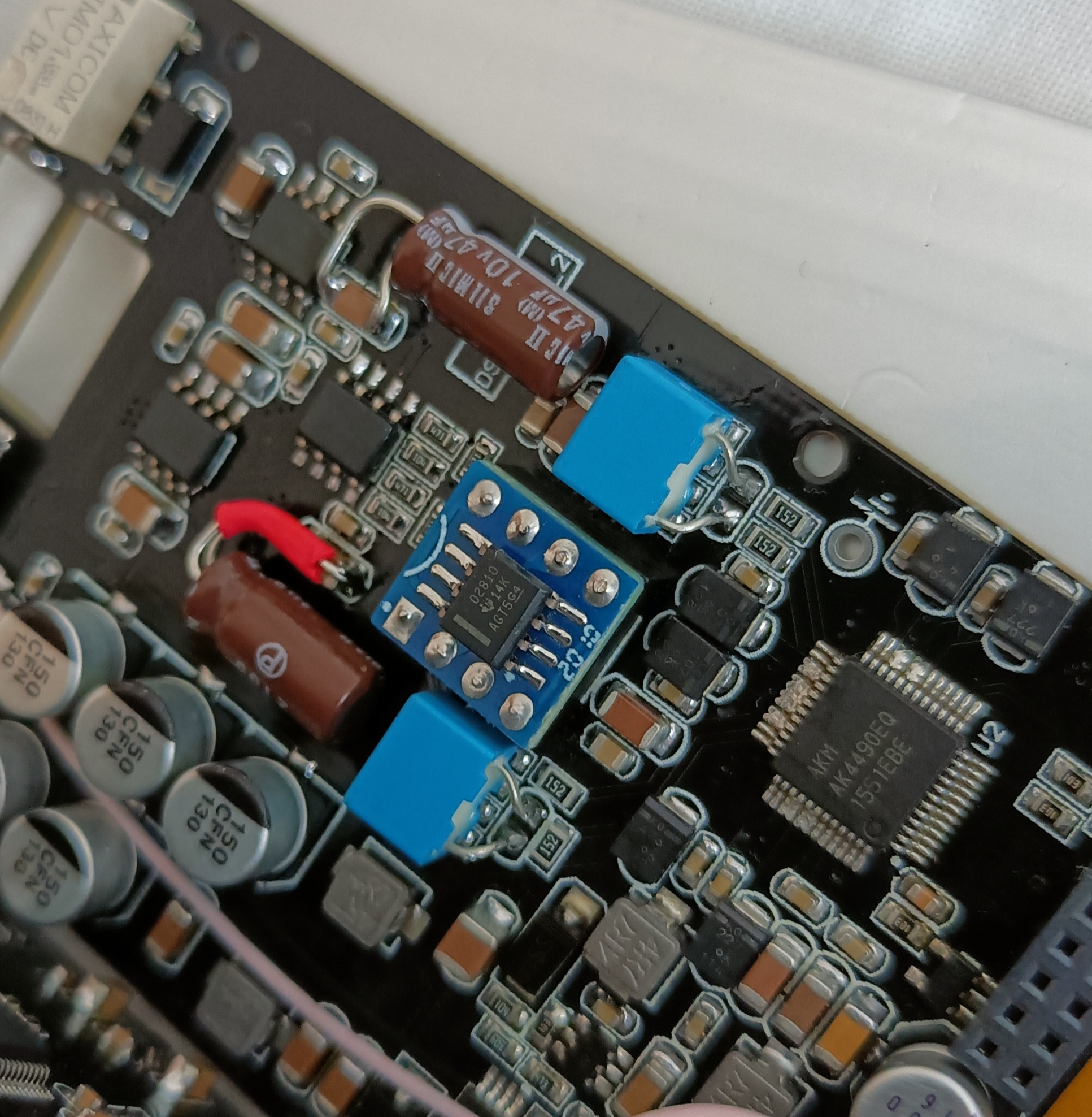
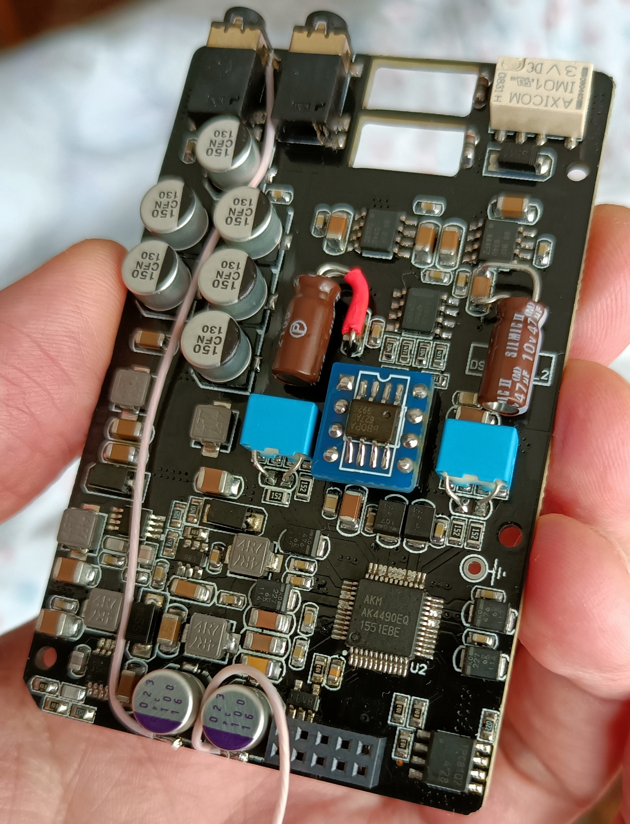
The ak4497 that I have has the same resistors positions in that MP1542 circuit, so I assume the two resistors that setup the MP1542 voltage to be in the same position, but if you want to be sure, you need to read the MP1542 datasheet and trace in your PCB to see if the resistors I marked red are the R1 and R2 in the datasheet circuit.
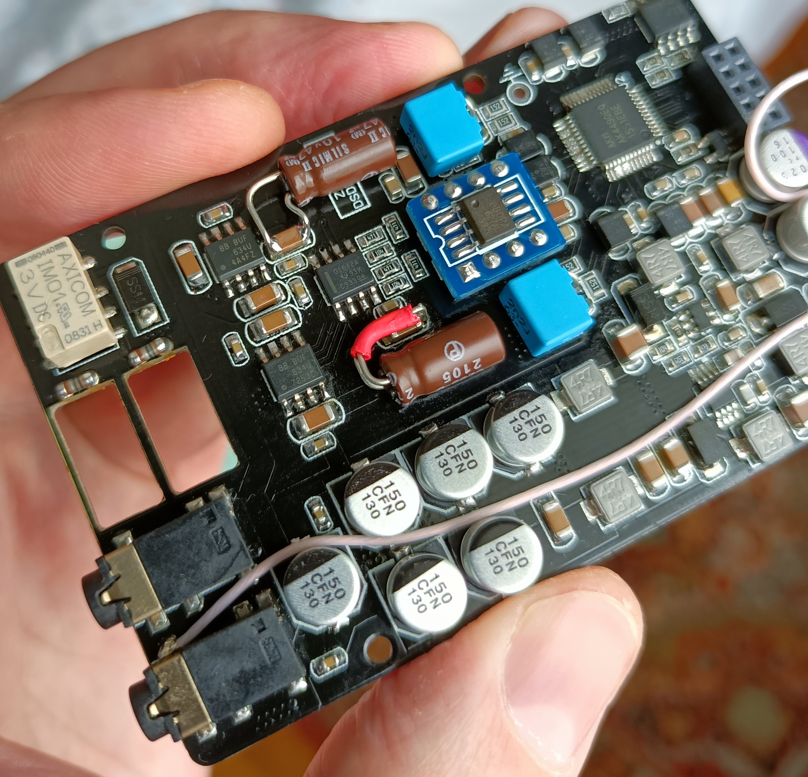
I marked in RED the 2 resistors that (I think) sets the voltage for the MP1542 boost convertor:
R1 = SMD resistor marked 224 = 220K
R2 = SMD resistor marked 473 = 47K
Vout = 1.25 × (1 + R1/R2) = 1.25x(1+220/47) = 7.10V


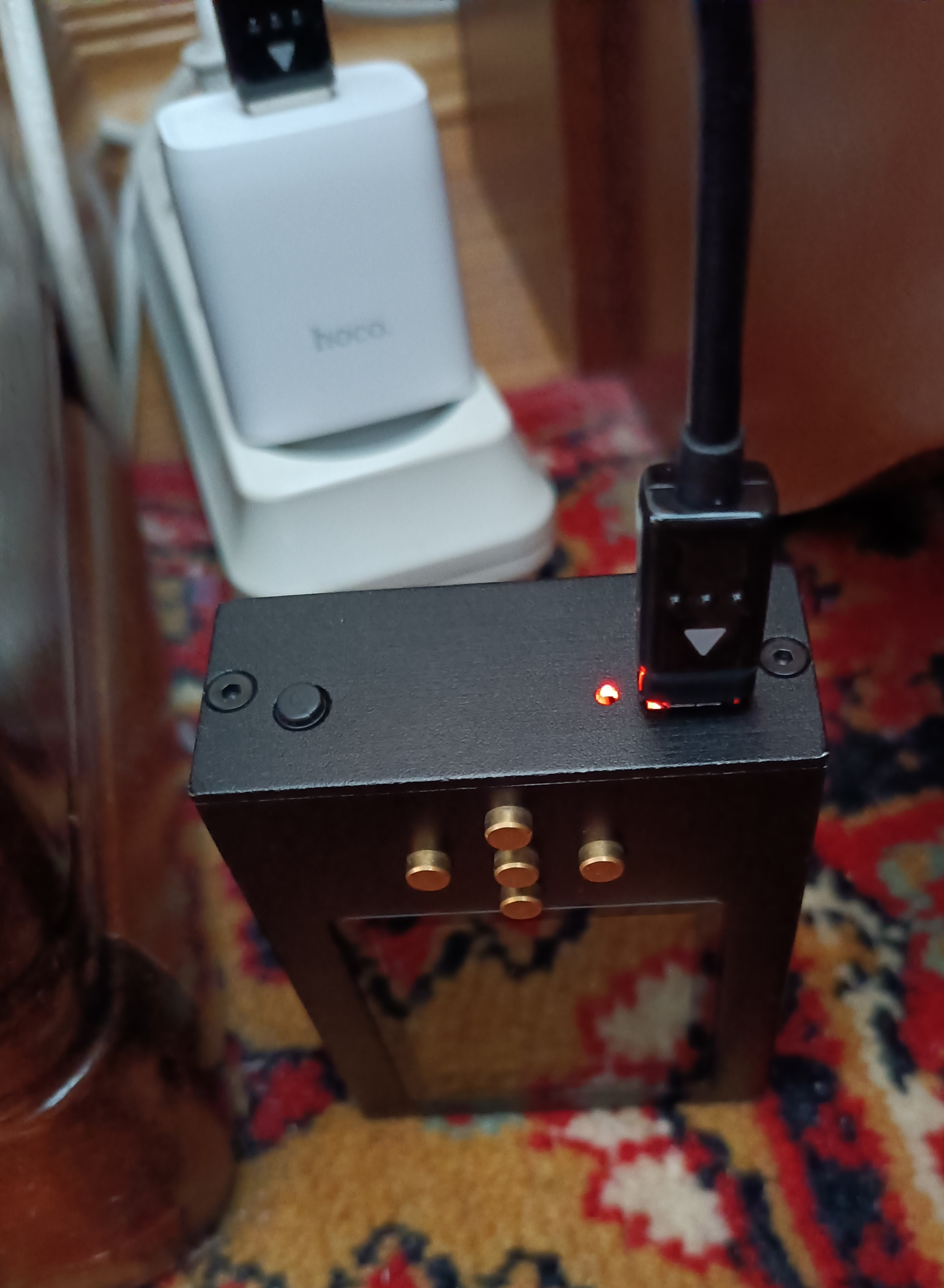


 the only contact I do was to the side (where is the rail that the PCB slides) also thinking, with one sheet of binding and the cooper it barely fit also thinking to change to an acrylic case but no money at the time... Or maybe drill holes to the back of the case.....
")
