The Stax SRM-002 mod thread

Apr 7, 2013 at 9:09 PM Post #18 of 53
you mean it is not a part of the system and you have to buy it separately?
 
Might as well just mod a battery pack to 5000mAH with power pigtail and call it good. The power pack can also work as desktop power supply ( run the amp while being charged via USB).
 
Apr 29, 2013 at 12:54 PM Post #21 of 53
A-cats - thanks for posting about the USB battery pack mod; very cool and I plan to do this one. Even as is, the pack was a great buy; was able to charge my cell phone overnight while off the grid; was at 100% next morning. Certainly smaller than the wallwart I'm transporting, and USB charge while in use makes it a win-win. 
 
From where did you order the protection circuit? Got a part number by chance? Oh, I did pop the top off my USB pack and it has a larger battery and no lead strip to add fake weight. Must be a few version floating around the web.
 
I do still plan to get around to the 002 mods you've described; at least the input and output cap portion. I actually took the 252A amp to the office so I could leave the 002 disassembled on the bench. Given my work schedule, that's as far as I've gotten.
 
Jan 21, 2014 at 7:23 AM Post #26 of 53
I'm not sure there will be much more space.  I'm guessing a lot of space is dedicated to the new rechargeable batteries and of course the DAC components in the unit with a converter.  
 
I'm looking forward to checking them out, and like the idea of some 002's set up for custom tips!
 
Jun 9, 2015 at 11:39 PM Post #29 of 53
Got to play with the 002 a little today.
 
Observations:
1) exterior: the plastic used, in both the amp and the headband, looks cheap. Not exactly low quality plastic, but feels somewhat "ordinary".. This is a stax, we have high expectations!
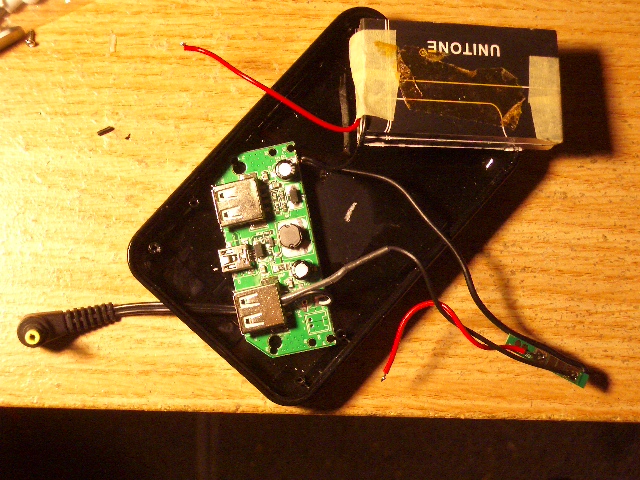
2) the amp stack onto the battery pack (the one in post #11) nicely. The battery pack is only slightly wider.
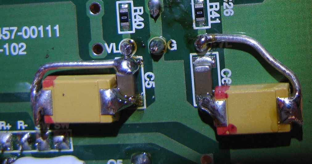
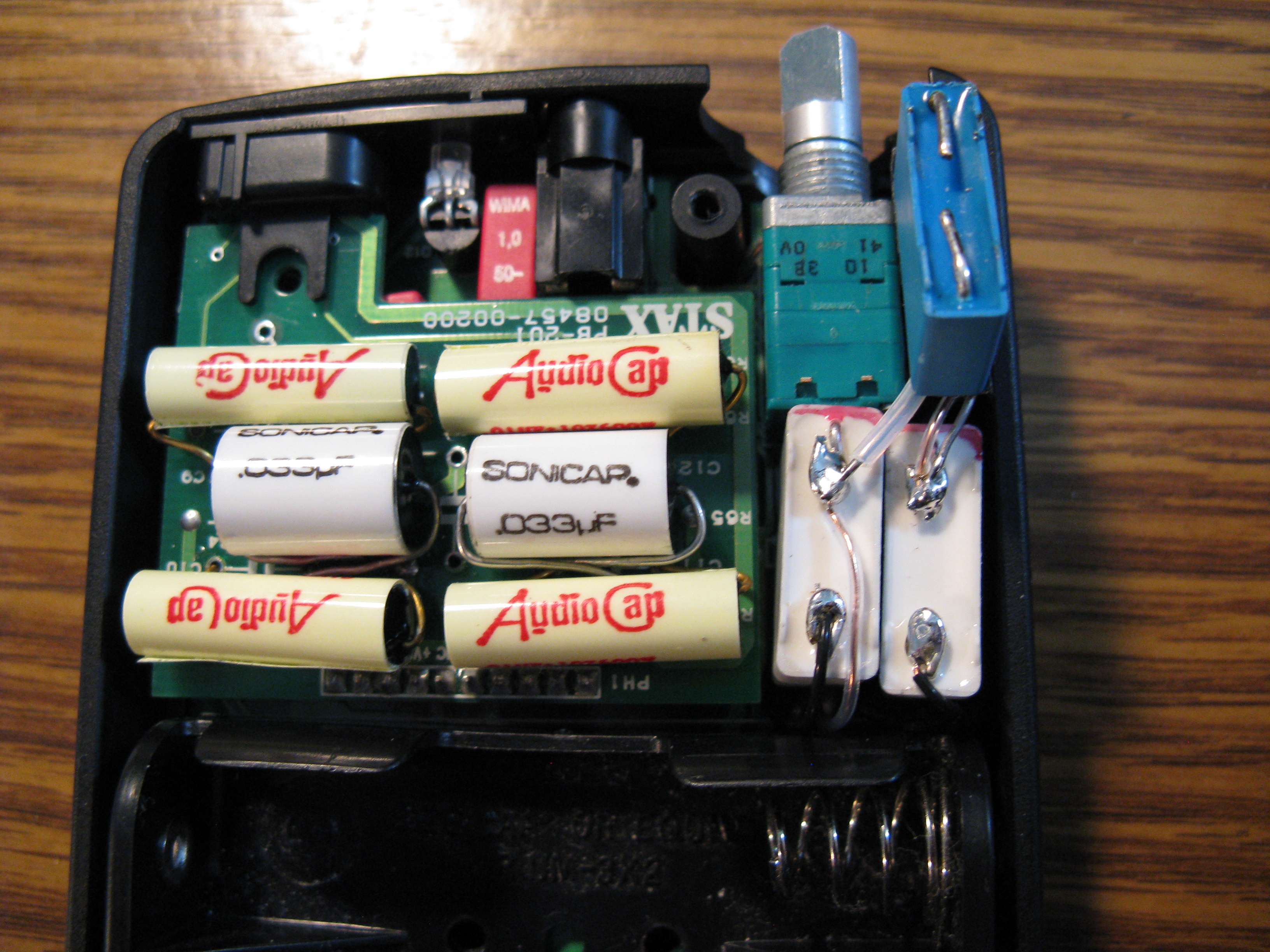
3) internally: actually, does not look cheap at all. Components are very well arranged (meaning: suitable for modding....:). Lots of surface mount parts.
4) internal space available for upgrade parts: somehow it feels like there is tons of room available and it might even be possible to install premium components (which can not be fitted into a 001), such as Teflon output caps (!). 
 
At a quick glance, my guestimate on the difficulty level of doing the mods:  if one just want to do the mid level upgrade (like the SuperFatCat 001 I have done before), I'd say 001 and 002 are about the same. Above that level, 002  has advantage, it will likely require less fiddling around to fit premium parts, allowing a more straight forward operation. The srm-002 is probably the better base amp if one wants to go all-out and push the limit.
 
*phones comparison, SR-001 vs. SR-002 (it will actually  be 003 vs. 003MK2 as I will be using 001 and 002 drivers with a 003 cable).
 
 
Experiment schedule:
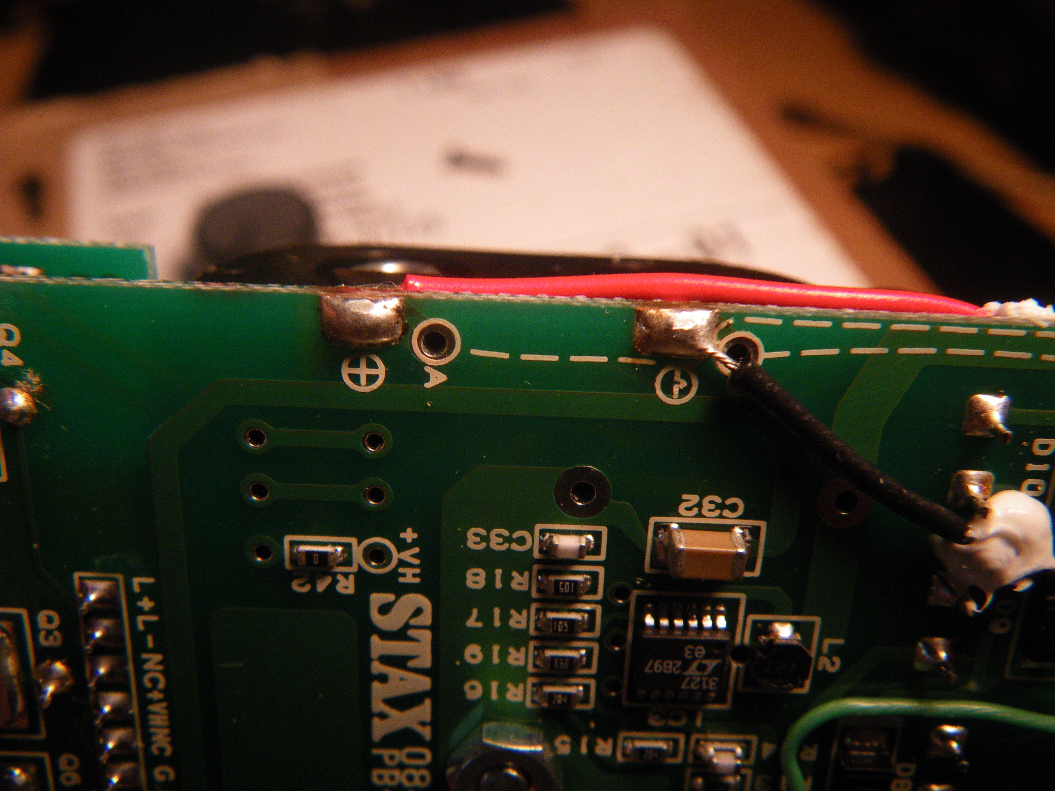
1) basic circuit investigation (to see if it is too different from the 001 circuit)
update:
-- the output stage uses different devices. instead of two 2sk117 and two 2sc3405 per channel, it has a 5-lead device in the place of 2sk117's, and use two 2sc6127 for output. The 5-lead device is only marked "x y".
-- the opamp stage looks about the same as what is in 001 (see Kevin Gilmore's schematic in the 001 thread), except the input resistor (connecting to the DC-blocking input caps) is 1k instead of 2k.
-- power supply section is roughly the same.
 
2) Op-amp experiment
update: will not happen anytime soon. during the mod preparation I damaged one of the 2sc6127 and it seems that they are only available from China, price is about $1 a piece but shipping will be slow....
 
3) Fitting of actual mod parts
update: Soniccraft is helping me to find the right size caps that can fit into the case.... It turned out to be not as easy as I thought, the 16mm max diameter requirement on input cap is still too small for most boutique caps to fit.
 
Jun 10, 2015 at 2:00 AM Post #30 of 53
some quick notes of available space:
*battery compartment area: by taking out the battery tray, has enough room to fit in a pair of (input) capacitors. Max cap size 16mm (dia) x 62mm (L).
 
*output daughter board:
-- resistors are 2mm height, if resistors stay on the top side, allows mod components with 8~10mm height (or dia).
-- if all resistors moved to the under side, the area closer to the battery compartment allows component height of 12mm or less; the area closer to the LED
allows 10mm. ( for output caps and high voltage reservoir caps).
 
*the space between daughter board and main board: after moving four 2.6M resistors to the underside of main board, there is 5mm space between boards ( which allows installing four 0.1uf/600v Epcos caps as high voltage rail reservoirs)
 
*underside of main board: max component height 3mm. Enough for extra surface mount tantalum caps as low voltage +/- rail reservoirs. Plenty of room to parallel them.
 

Users who are viewing this thread

Back
Top