The DIY'rs Cookbook
May 7, 2020 at 1:20 PM Post #1,636 of 1,974
Just solder each resistor from + to ground (TRS) or + to — (XLR) for each channel.
Thanks again for this. I have done w/ XLR and it works a treat.

Regarding the TRS, I think I may have misunderstood - so just checking:

A) 2 resistors, each L>Ground and R>Ground.
B) 1 resistor, just L(I think+)> Ground.

I wired A (2 resistors) and the multi-meter shows the 100% cross-connection, so I came back to check this note... So I think I did A and you meant B? How dangerous is a little knowledge in the wrong hands ...??

Tx again for indulging!
 
May 7, 2020 at 6:54 PM Post #1,637 of 1,974
Also, duplex receptacles should be contact cleaned (TURN OFF:scream:) like we do our interconnects, etc. Cotton pipe cleaners fit nicely. After dry polishing, any traces of cotton can be sucked out with a vacuum cleaner hose.
Ah yes, another one us who will go to any length to push the edges of the envelope and make sure those pesky teeny tiny hairs won't contaminate our addiction for tweako tunes…
hahahahahahahahahahahhaha

JJ
 
May 7, 2020 at 6:57 PM Post #1,638 of 1,974
Thanks again for this. I have done w/ XLR and it works a treat.

Regarding the TRS, I think I may have misunderstood - so just checking:

A) 2 resistors, each L>Ground and R>Ground.
B) 1 resistor, just L(I think+)> Ground.

I wired A (2 resistors) and the multi-meter shows the 100% cross-connection, so I came back to check this note... So I think I did A and you meant B? How dangerous is a little knowledge in the wrong hands ...??

Tx again for indulging!
Option (A)
All you need are 2 resistors one for each channel from hot (+) to the common ground in the TRS connector.

JJ
 
May 7, 2020 at 7:37 PM Post #1,639 of 1,974
Bill, you're too hard on yourself :wink:

Mine fell all the way out a long time ago. But on the plus side, no further nervosa about them possibly being loose. :)
 
May 8, 2020 at 2:37 AM Post #1,640 of 1,974
The title of this post is…
Don't you just hate it when that happens…?

So that $250 duplex receptacle is still in the process of blossoming and continues to reveal yet more inner - outer - lower-mid-high - soundstage - REALNESS - HOLO - SDSG - I5 and probably a few other descriptors. (See the link in sig line for definitions.), AND set new records, all the way around.

But I'm gunna hold off making a more complete evaluation until the shifts and morphing of the SQ has stabilized and I can more fully describe what I'm hearing.

But as of now the bar has risen in unexpected and wonderous ways that require new words, or concepts, or perceptual frameworks, or sumpt'n…

But the end results, at least thus far are, now I just can't return this $250 duplex receptacle and I may need to add another, just to see what happens.
Talk about a budget buster, and JUST for duplex receptacles…

Don't you just hate it when that happens…?

JJ :thinking: :ksc75smile:
 
Last edited:
May 10, 2020 at 7:01 AM Post #1,641 of 1,974
So I'm gunna take a stab at describing what the changes are, at least thus far.
I say that because it appears these $250 duplex'rs will take several hundred hrs. to fully stabilize and 'show their stuff'.
Well that is if they follow a recurring pattern from other such mods and experiments.
And so far I guess I'm in the 250hr range ±.
And it may take in excess of 400hrs, but we'll see.

Right now the SQ has changed every single descriptor and audio term I have come up with to describe what I hear, and they ALL have jumped up at once.
This is a 1st.
Usually several will be improved or even all of the 'primary' ones that make immediate differences in SQ, but they ALL stepped up at once which is akin to the saying 'the Sum is greater than all of the parts together'.

Think, stripping away a veil so 'broadband' in ALL acoustic aspects that everything, every single acoustic/sonic trait just got 'BETTER', all at once.
Another way to describe it is, a slew rate & dynamic range & FR smoothing, all stepped up, along with a tLFF reduction, all at once.

Attack, LEDI, C3, soundstage stability, Realness, Holo, 'voice' authenticity, presence, the list goes on and on…

And in my truest Inspector Clueso voice…
I alvaise except ze shallanngé

So I'm going to see what happens when I use a pair of these $250 duplex'rs as termination from a couple of different ac supply configurations.
It just might be that bypassing the existing isolation &/or voltage step down xfmrs in place, might prove to be beneficial.

With this newly attained, added degree of resolution, it should be much easier to hear any differences, either way (better or worse).

Lastly what I hear is EVERYthing has more there, there, but not more exaggerated nor out of balance with everything else within the soundstage.
It's that old, 'more of the acoustic energy that is created, is aligned and focused where it needs to be, and NOT where it shouldn't be', thing.
On steroids…

JJ
 
May 11, 2020 at 5:59 AM Post #1,642 of 1,974
I figure most of you have never even heard of a Western Electric 124 amplifier, at least before reading a bit about it in this thread.

And so I'll provide a bit more of a 'up close and personal' looky see into this 'odd ball' amp.

ƒ'124 amp pic.jpg

This is a ≈12-20watt/ch 'industrial' amp designed about 80 years ago by Western Electric.
It uses a pair of 348A drivers and a pair of 350B as output tubes.
These are pentode tubes, meaning they have 2 more internal parts called screens in addition to the 3 primary parts, the plate, the grid and cathode.
The filaments are 'assumed' so they aren't counted.

However, using 'real' NOS WE tubes would make this a 10-20K$ amp, which is simply not gunna happen.
So instead for each amp I'll be using a pair of 6C6 drivers and a pair of 6L6GC as the output tubes, at least to start with.

This amp is a 'novel' push-pull design with 'unique' feed back like circuits used to 'tame' and operate the pentodes more as triodes.
It sounds complex and it is, and so much so that I only have a tenuous grasp of the how and what and why of this circuit.
But that won't stop me from trying to convey not only it's uniqueness but its strengths and suitability as a speaker amp for efficient speakers, especially in a desktop/near field arrangement.

Rarely will you hear of pentode tube amps used AS pentodes and that is because pentodes have 'performance foibles' when used AS pentodes.
What usually happens is they are 'strapped' as triodes (meaning wired and operated as triode tubes) instead, to avoid these 'performance foibles'.

The 6L6 'parts bin' amp is wired sorta like this except it is wired in 'ultralinear' mode (which also tends to 'tame' the 'performance foibles'), but it could be easily re-wired for triode mode.
But the power output drops by ≈1/2 or more when this happens.

The reason pentodes are used is they can crank out more power and a whopping 20 watts, back in the early 40's was a 'big deal' indeed.
And even today with speakers that are in the 100dB/w (±5dB/w), 20 watts, especially in a near field setup, has plenty of headroom with the added punch that plenty of reserve can enable.

This amp also reflects the specifications that were available back then and so by today's 'standards' might seem like a step backwards.
Except that the SQ of the amp makes these specs almost meaningless.
To wit, 12 watts @ 2.0% @400Hz THD and -37dB s/n relative to 0.001watt.
These specs are based upon full (rated) output, and where we will use this amp, at < 5watts, the distortion etc, will be far less, like orders of magnitude less.

This is a 'normal' characteristic of tubes, where as full power is approached, the distortion tends to 'sky's out', (is non-linear, meaning it rises very rapidly).
And the very nature of the harmonic content is also a BIG factor in how the amp 'sounds', especially when pushed, which we really won't need to do in the first place.

So this amp project is getting parts ordered and tubes collected and will be built as mono-blocks, which is how the amp was designed, since stereo wasn't even a twinkle in anyone's eyes at that point in time.

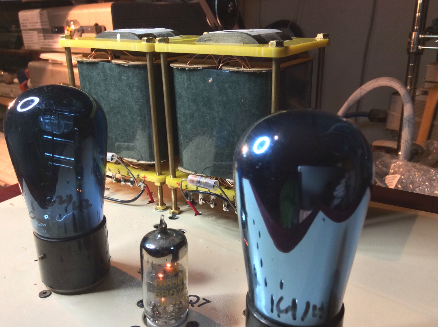
So my collection of 6C6 tubes thus far…
IMG_2901.jpg
There are 4 Sylvania's, 4 Arcturus's, a matched pair of National Union's, with a smattering of Tung-Sol, Hytron, and Cunningham tubes.

6C6's have that 'button' on top of the tube for connection to the grid for this tube, which means it only carries the input signal (0-4volts max).
This is a good thing since I have 'curious cats' who will sniff any new stuff and if we used tubes where the button on top carried plate voltage (B+ of 350vdc), well, there would be cat shrieking, at least once.
Which we don't have to deal with… hahahahahahahaha :ksc75smile:

This will be a rather unique build and for more reasons than outlined here thus far.
It promises to be a 'stellar' performer with a heritage back to the heyday of tube design by the eminent Western Electric company and without the outrageous expense of using WE tubes.

JJ
 
Last edited:
May 18, 2020 at 5:52 AM Post #1,643 of 1,974
Morgan Jones - Building valve amplifiers
"Beam valves and mains transformers. Beam valves deliberately focus their current into thin sheets that pass largely unintercepted between the horizontal wires... "

What does that "beam valves" mean?
 
May 18, 2020 at 6:11 AM Post #1,644 of 1,974
I've not heard that particular term before.
I have heard of beam forming or focusing screens which are used in tetrodes and pentodes.

And if this is similar then these screens are used to add more electron 'flow' to increase the power of the tube.

Perhaps others will know more specifics.

JJ
 
May 18, 2020 at 6:30 PM Post #1,645 of 1,974
Morgan Jones - Building valve amplifiers
"Beam valves and mains transformers. Beam valves deliberately focus their current into thin sheets that pass largely unintercepted between the horizontal wires... "

What does that "beam valves" mean?

It means that it is a tube with beam forming plates instead of a suppressor grid like a pentode would have.
 
May 27, 2020 at 5:13 AM Post #1,646 of 1,974
So an update.
The Purp-Amp has reached a degree of stability in terms of SQ, but still does require fussing with the knobs and adjustments from time to time, in order to keep in it the sweet spot.
I figure it has to do with thermal mass and stability along with a bit of wear and tare on some of the parts.

But as a 'research' tool and 'demonstrator' it has proven not only it's worth, but also how far we can push the SQ and in which ways.
And not just in terms of basic design implementation changes, but also how effective my secret sauce 'mixes' can be and in which ways.
Along with how 'sensitive' it has become to external tweaks and such.
Not to mention the net effect that tubes can make to the overall SQ.

All of this is part of the learning curve dealing with figuring what does and doesn't make improvements to the overall musicality of this amp.

I did some back of the cocktail napkin math and figured that at ear splitting peak SPL's this amp delivers ≈ 0.39w into my 800's which is roughly 1/2 of the tubes rated output.
Normal 'average' power being used at those same levels are ≈0.0008w

But at 'normal' listening levels there are peak levels of ≈0.01w and ≈0.000056w 'average' power is being used.

And all of these calculations are based upon a 32Ω output impedance.
And the 800's use but a fraction of even these power levels.

In short, for mid to high Ω HP's, the amount of power used is minuscule and these results also tell us that the design of the amp MUST be able to deliver, with integrity, ALL of the small signals, because the music as delivered to the HP's is ALL in these mW ranges.

This is also why the 71A output tube with a MAX power rating of 0.79w can 'do the job' and not run into clipping, even at deafening SPL's.

JJ
 
Last edited:
May 27, 2020 at 11:06 AM Post #1,647 of 1,974
So an update.
The Purp-Amp has reached a degree of stability in terms of SQ, but still does require fussing with the knobs and adjustments from time to time, in order to keep in it the sweet spot.
I figure it has to do with thermal mass and stability along with a bit of wear and tare on some of the parts.

But as a 'research' tool and 'demonstrator' it has proven not only it's worth, but also how far we can push the SQ and in which ways.
And not just in terms of basic design implementation changes, but also how effective my secret sauce 'mixes' can be and in which ways.
Along with how 'sensitive' it has become to external tweaks and such.
Not to mention the net effect that tubes can make to the overall SQ.

All of this is part of the learning curve dealing with figuring what does and doesn't make improvements to the overall musicality of this amp.

I did some back of the cocktail napkin math and figured that at ear splitting peak SPL's this amp delivers ≈ 0.39w into my 800's which is roughly 1/2 of the tubes rated output.
Normal 'average' power being used at those same levels are ≈0.0008w

But at 'normal' listening levels there are peak levels of ≈0.01w and ≈0.000056w 'average' power is being used.

And all of these calculations are based upon a 32Ω output impedance.
And the 800's use but a fraction of even these power levels.

In short, for mid to high Ω HP's, the amount of power used is minuscule and these results also tell us that the design of the amp MUST be able to deliver, with integrity, ALL of the small signals, because the music as delivered to the HP's is ALL in these mW ranges.

This is also why the 71A output tube with a MAX power rating of 0.79w can 'do the job' and not run into clipping, even at deafening SPL's.

JJ
Great explanation, JJ. Should be real disappointing to the “lotsa wattsa” crowd. :gs1000smile: HAHAHA
 
Last edited:
May 27, 2020 at 7:35 PM Post #1,648 of 1,974
Great explanation, JJ. Should be real disappointing to the “lotsa wattsa” crowd. :gs1000smile: HAHAHA
“lotsa wattsa” hahahahahahahahahahahahahha

And yeah the amount of power we need is teeny tiny and those peak measurements were taken while playing bass heavy tracks with my DSP on and the sub bass (14Hz) boosted by +14dB.

Kinda makes ya wonder don't it?
hahahahahahaha

JJ
 
May 29, 2020 at 9:18 PM Post #1,649 of 1,974
“lotsa wattsa” hahahahahahahahahahahahahha

And yeah the amount of power we need is teeny tiny and those peak measurements were taken while playing bass heavy tracks with my DSP on and the sub bass (14Hz) boosted by +14dB.

Kinda makes ya wonder don't it?
hahahahahahaha

JJ

Math is hard. I'll just take your word for it. :) :)
 
May 29, 2020 at 9:34 PM Post #1,650 of 1,974
It all boils down to E=IR (E)voltage = (I)current x (R)resistance.
I measure the voltage, both peak and average and use the R of 32Ω to figure the current for those voltages.
Then I multiply the voltage x current to determine the wattage.

This calculates numbers that are representative of the conditions as music is playing.

And really trying to condense the dynamic that is music into a snap shot of a single number is like herding cats, its kinda shows what is happening but is not completely inclusive nor truly representative of what is truly happening in real time.

JJ
 
Last edited:

Users who are viewing this thread

Back
Top