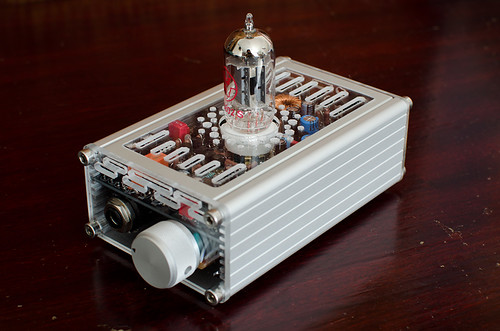
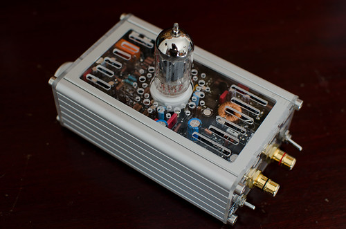
the CTH (Compact Tube Hybrid) Rev A thread...
Mar 24, 2012 at 11:28 AM Post #436 of 607
Thanks cfcubed. May end up just doing that. I'm trying to learn what I can about the circuit so I can be more targeted in my efforts. But yea, it is frustrating. May be time to shot gun it. Sachu is pretty dialed in with troubleshooting, so I'm hoping he'll chime in.
 
Mar 24, 2012 at 4:56 PM Post #437 of 607
I'm the not the best when it comes to troubleshooting this amp, but I'll second the idea of taking the kitchen sink approach. You could test each BJT with a diode test. Look up how to test a BJT on the net and whatever BJTs fail pull those. But that might not solve the problem. So pulling all the BJTs out should do the trick.
 
Apr 1, 2012 at 10:51 AM Post #438 of 607
I'm pretty much finished with mine, here it is:


Pretty much a standard build, other than the odd board placement and a few of the components. Made the acrylic parts myself, as you can see. :) 
The potentiometer has a switch in it, thought about using it as a power switch, but didn't. Maybe I could use it with the relay to avoid that pop when turning off?
 
Apr 1, 2012 at 1:02 PM Post #440 of 607
Scy -- cool build. One more the more interesting builds I've seen thus far. What did you use to cut the plexiglass?
 
Hey Mr R did you ever finish your build? The shotgun approach is definitely the way to go when fixing this amp. You might have a misplaced part somewhere. It's easy to do.


Apr 1, 2012 at 1:06 PM Post #441 of 607
No, not yet Mullet. I changed Q4S, Q6S, Q3S and Q5S yesterday - no luck. I've got 24V out of the reg, but no output on OL or OR. Any suggestions on where to shotgun next?
 
Apr 1, 2012 at 5:15 PM Post #442 of 607
Thank you for your comments.
Quote:
Scy -- cool build. One more the more interesting builds I've seen thus far. What did you use to cut the plexiglass?


Nothing fancy really, a micro drill and a drill press, files and sanding paper. It's quite laborious to get anything done this way though, I might get a small compound table if I find enough use for it.
 
Apr 1, 2012 at 8:58 PM Post #443 of 607
What about the IC2S? I think CF3 also suggested taking out all of the BJTs from Q4L/R to Q9L/R. I know it sucks. Been there before. But taking them all out and replacing them with known good BJTs *might* work. WIsh I knew more about this to help you dial in on the problem. Like you said before hopefully Sachu can jump in and assist.
 
Apr 1, 2012 at 9:24 PM Post #444 of 607
All good suggestions Mullet. It's actually not so bad. I've gotten a lot better at BJT removal than I ever wanted 
blink.gif

 
May 4, 2012 at 12:37 AM Post #445 of 607
I've finally started my build, so far there's not enough on the board to do any testing, so it must be going great!
biggrin.gif

 
As I was looking for various things, I realised I didn't get R5H. I'm probably missing something on the CTH website or in this thread - but what value should it be? I understand it changes the voltage on the tube, but which one, the 6.3 V or the 12.6 V? And what resistor do I need to maintain the 6.3/12.6 choice?
 
Thanks!
 
mrhk13
 
May 4, 2012 at 1:46 AM Post #446 of 607
R4H and R5H only need to be populated if you intend to have more than 2 heater voltages. R1H is fixed. R2H and R3H usually are 9.31kΩ and 7.15kΩ for 12v and 6.3v.
 
May 4, 2012 at 9:19 AM Post #447 of 607
Thanks Mullet... This morning I checked RevA schematics rather than the original schematics on the Cavalli Audio site and d'oh! I feel a bit of an idiot. It makes more sense now. I need to look back at my board: more possible voltages must mean more pads to connect a three-way/four-way switch. Completely missed that last night.
 
Clearly, I shouldn't have posted the message, but rather gone to bed, let the lead-fumes clear and look again with fresh eyes. Lesson learned.
 
Humbly-
mrhk13
 
May 27, 2012 at 4:08 PM Post #449 of 607
Just curious about cleaning the board after soldering is done. Normally, I'd just use 99% alcohol and a tooth brush. Then I'd let it dry and that's it. The board would be kind of sticky, but I ignored that. Recently, I built a GrubDAC and it was suggested to also run some hot water on the board to clean off the excess stickyness. The person said it was safe to do so. However, I've also read that you wouldn't want to do this with certain parts installed like a pot, or devices like a mosfet. What about the BJTs that are installed on the CTH, or Q1P, ICP, and ICH? Is it safe to put the whole board with all parts installed in an alcohol bath and then run the board under hot, soapy water to fully clean the board?
 

Users who are viewing this thread

Back
Top