The Apple diyMod: My Take on the Famous iMod [56k killer] Featuring 3G, 4G, 5G and nano 1G!
Jan 9, 2008 at 5:04 AM Post #661 of 3,220
Quote:

Originally Posted by CAvanessia /img/forum/go_quote.gif
Please keep us updated with the RWA iMod vs. diyMod.
cool.gif


If anyone is interested in my 220uf BG dock, please send me a PM.


Many thanks to the guidence for the ipod mod
as i will be ordering some dock
but i have found a site in china but need to order 1000 pcs who want to share?
Unless i am running a business like ALO .......

looks like i dun need 1000 pcs any way will need to order 20 pcs
for my personel use
 
Jan 10, 2008 at 3:32 AM Post #662 of 3,220
What site are you using to order those iPod connectors?

I don't know if I mentioned this, but I ripped off the solder pads on my friend's iPod 5G when diyModding it. Silly me, I didn't secure the wires, so all that tugging was no good for the super sensitive board. This warning goes to all diyModders: [size=xx-large]secure your wires![/size] Now I get the joy and pleasure of soldering straight to the Wolfson DAC and straight to the iPod dock. Surely, I enjoy skill competitions as much as the next guy, but it's a hassle very many of you will want to avoid (that excludes ruZZ.il
smily_headphones1.gif
). With the iPod 5G, it's trickier with the metal frame, though possible. There is a tape wrapped overtop of the dock, so you have to remove that before assigning wires to any of the pins. I believe all iPods share this characteristic.

Remember, [size=xx-large]secure your wires![/size]
 
Jan 10, 2008 at 3:55 AM Post #663 of 3,220
Many thanks to everyone on this thread, it's been unbelievably interesting and helpful.

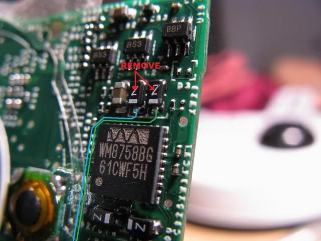
I took the dive and started the process on a 5g-video and I got the two caps near the DAC off. Some pics here:

side.jpg

closeup2.jpg


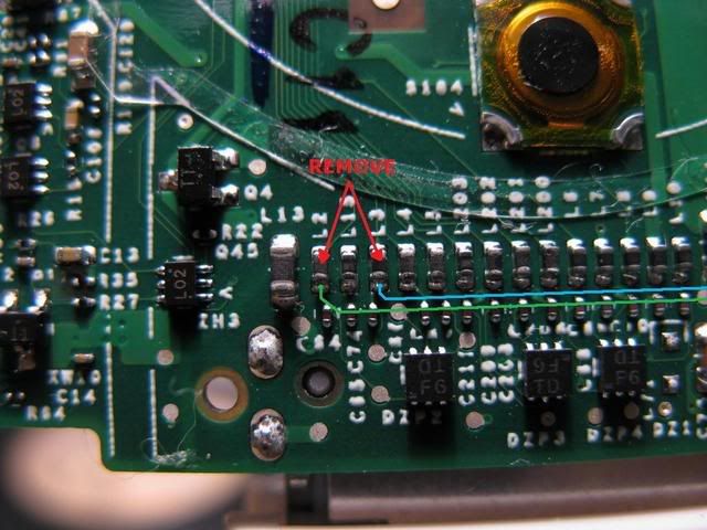
As I turned to the dock side of things I noticed some traces going to bare metal pads (green arrows). Specifically:
frontOn.jpg

closeup1.jpg


I confirmed with a multimeter that L2 and L3 are connected to these pads (green arrows). In measuring resistance I found that they both have 1 Ohm resistance stably. Meaning that little things pointed at with the red arrows are probably resistors. I also confirmed with multimeter that the top series of pads newly exposed near the DAC are indeed connected to the metal pads (green arrows). Obviously the lower series of newly exposed pads by the DAC are not connected (but confirmation is good to ensure no crossbridging).

A few questions:

1) Can we just solder from the DAC to these pads and then get rid of L2/L3?

2) Is it necessary to kill L2/L3 if we have removed the Caps up next to the DAC? Since we should have theoretically killed the circuit up top anyway why do we have to kill it again near the dock?

If the answer to both of these questions is 'yes', then I think this would be the most simple way to mod the 5g.
1) Take out the two caps near the DAC
2) Solder thin wires from the newly exposed pads near the DAC to the metal pads.

From previous experience from surface soldering I would urge everyone to tape the wires down before soldering and to use the thinnest wires possible. Lifted pads are NOT easy to fix.
 
Jan 10, 2008 at 5:17 AM Post #664 of 3,220
Quote:

Originally Posted by aaronylee /img/forum/go_quote.gif
Many thanks to everyone on this thread, it's been unbelievably interesting and helpful.

I took the dive and started the process on a 5g-video and I got the two caps near the DAC off. Some pics here:


As I turned to the dock side of things I noticed some traces going to bare metal pads (green arrows). Specifically:

I confirmed with a multimeter that L2 and L3 are connected to these pads (green arrows). In measuring resistance I found that they both have 1 Ohm resistance stably. Meaning that little things pointed at with the red arrows are probably resistors. I also confirmed with multimeter that the top series of pads newly exposed near the DAC are indeed connected to the metal pads (green arrows). Obviously the lower series of newly exposed pads by the DAC are not connected (but confirmation is good to ensure no crossbridging).

A few questions:

1) Can we just solder from the DAC to these pads and then get rid of L2/L3?

2) Is it necessary to kill L2/L3 if we have removed the Caps up next to the DAC? Since we should have theoretically killed the circuit up top anyway why do we have to kill it again near the dock?

If the answer to both of these questions is 'yes', then I think this would be the most simple way to mod the 5g.
1) Take out the two caps near the DAC
2) Solder thin wires from the newly exposed pads near the DAC to the metal pads.

From previous experience from surface soldering I would urge everyone to tape the wires down before soldering and to use the thinnest wires possible. Lifted pads are NOT easy to fix.


I am not an expert but I will attempt to answer with what I know.

1) I think someone else did not remove L2/L3 and there were some undesired effects. My memory may be wrong. If the L2/L3 pads after removal still have connection to the new pads, I don't see any harm in using the new pads especially if they will be easier.

2) It isn't necessary to remove caps/resistors/whatever they are (red arrows), but I was informed by someone in this thread that these parts may degrade sound in theory. If I recall correctly there is something about the signal traveling out of the dock and some parts of it coming back.... or something like that.

Lets just wait for someone more knowledgeable to jump in here.
biggrin.gif
 
Jan 10, 2008 at 5:20 AM Post #665 of 3,220
Interesting find!! It would seem like a yes to both of those questions like you said. It wouldn't hurt to give it a shot...that would make things a whole lot easier!
 
Jan 10, 2008 at 9:04 AM Post #667 of 3,220
Quote:

Originally Posted by aaronylee /img/forum/go_quote.gif
Many thanks to everyone on this thread, it's been unbelievably interesting and helpful.


You're welcome.
smily_headphones1.gif


Quote:

Originally Posted by aaronylee /img/forum/go_quote.gif
A few questions:

1) Can we just solder from the DAC to these pads and then get rid of L2/L3?

2) Is it necessary to kill L2/L3 if we have removed the Caps up next to the DAC? Since we should have theoretically killed the circuit up top anyway why do we have to kill it again near the dock?


The reason it was decided to desolder L2 and L3 really comes down to minutiae. The ultimate bearing on the sound probably won't be much, but it follows good theory to remove those parts. Going back to the highway analogy, when you open up an exit that leads nowhere, you still take a few cars away from the highway that needed to get somewhere, even if it is only a small fraction of the entire traffic population. Close off the exit, get as many people moving in as little time possible since nobody likes traffic jams. In this case, it's both our way and the highway.

Quote:

Originally Posted by aaronylee /img/forum/go_quote.gif
If the answer to both of these questions is 'yes', then I think this would be the most simple way to mod the 5g.
1) Take out the two caps near the DAC
2) Solder thin wires from the newly exposed pads near the DAC to the metal pads.


Whatever the diyModder is comfortable with. It is a challenge removing those SMD parts, and just now I soldered my diyMod wires straight to the dock which was a huge 3 hour headache. I think I did a really good job soldering, but the final fit isn't as pretty as it will be for most. I was about to buy a broken iPod to swap parts, but soldering straight to the QFN28 and dock pins was a much cheaper way to party. One way is easier, but whatever happened to the endless pursuit of perfection? Figure out which one is best for you.

Quote:

Originally Posted by aaronylee /img/forum/go_quote.gif
From previous experience from surface soldering I would urge everyone to tape the wires down before soldering and to use the thinnest wires possible. Lifted pads are NOT easy to fix.


Amen and hallelujah, brother. Amen and hallelujah.
 
Jan 10, 2008 at 9:26 AM Post #668 of 3,220
I think open ended caps connected to a sigal line may have more effect than open ended inductors.. since the caps effect is led by voltage, and the inductors by current.. since there is actually a voltage swing on an open ended device, there may be some effect.. though not so with an open ended inductor, where the current is almost non existent.. anyway, just a thought. maybe I'll scope it out sometime
biggrin.gif
 
Jan 10, 2008 at 12:03 PM Post #669 of 3,220
Quote:

Originally Posted by joneeboi /img/forum/go_quote.gif
Yeah, ishtob put the caps in his nano, but they are popping out the side for those that don't mind. We'll eagerly await your numerous high resolution, how-to pictures of the 3G.
smily_headphones1.gif


I'd been planning to doc what I do even before this prodding
smily_headphones1.gif
It'll be good to have this as a ref thread for the various efforts (accumulated experience, etc).

Just wanted to say I decided to order one of those new 850mAh ipod *mini* batteries for my 40GB 3G - This should yield a 5mm x 5mm x 30mm channel (approx) for parts in my 3G. I'll be doing the mod w/5x7 22uf BGs & ref resistors and trying feed through existing lineout.

Re: Secure wires - YES, the moment I'm sure of the connections I'll be using that hot glue gun
smily_headphones1.gif
 
Jan 10, 2008 at 4:03 PM Post #670 of 3,220
Quote:

Originally Posted by joneeboi /img/forum/go_quote.gif
FatHairyWomyn:

Love the forum handle.

vvs_75's Sonicap dock is meant to replace the BGs so that one can enjoy the fruits of different caps' labour. BGs are known for their quality and specs, but should one prefer a different sounding dielectric or brand, they can do so with the diyMod.

I've spent the past two days working on my PIMETA and an A47. The PIMETA is for my dad, which he greatly appreciated *wipes tear*, so I'll have the A47, a Mini^3, an RA-1 Clone, and my Millett Hybrid MAX to "roll" with my diyMod. I really like the sound of the PIMETA and A47, but I just don't have enough opamps to enjoy them at the same time. I'm sticking to the BGs for my diyMod, so now I don't know what I'll do with those $10/ea Vitamin Qs. I'm sure I can figure something out. I gotta grab some OPA2227s. Now I just need time to sit down and listen to them all.


Awesome man glad you like it,

I appreciate ALL the help from you and others on this Board and am glad I found it (the site).

For the record I fully understood that there had to be something there just wasnt sure if it was BG and Sonic caps

Thx All.
 
Jan 10, 2008 at 5:05 PM Post #671 of 3,220
Quote:

Originally Posted by aaronylee /img/forum/go_quote.gif
Many thanks to everyone on this thread, it's been unbelievably interesting and helpful.

I took the dive and started the process on a 5g-video and I got the two caps near the DAC off. Some pics here:

side.jpg

closeup2.jpg


As I turned to the dock side of things I noticed some traces going to bare metal pads (green arrows). Specifically:
frontOn.jpg

closeup1.jpg


I confirmed with a multimeter that L2 and L3 are connected to these pads (green arrows). In measuring resistance I found that they both have 1 Ohm resistance stably. Meaning that little things pointed at with the red arrows are probably resistors. I also confirmed with multimeter that the top series of pads newly exposed near the DAC are indeed connected to the metal pads (green arrows). Obviously the lower series of newly exposed pads by the DAC are not connected (but confirmation is good to ensure no crossbridging).

A few questions:

1) Can we just solder from the DAC to these pads and then get rid of L2/L3?

2) Is it necessary to kill L2/L3 if we have removed the Caps up next to the DAC? Since we should have theoretically killed the circuit up top anyway why do we have to kill it again near the dock?

If the answer to both of these questions is 'yes', then I think this would be the most simple way to mod the 5g.
1) Take out the two caps near the DAC
2) Solder thin wires from the newly exposed pads near the DAC to the metal pads.

From previous experience from surface soldering I would urge everyone to tape the wires down before soldering and to use the thinnest wires possible. Lifted pads are NOT easy to fix.


so from WM chip to the pad which is for which?
any idea?
 
Jan 10, 2008 at 7:57 PM Post #673 of 3,220
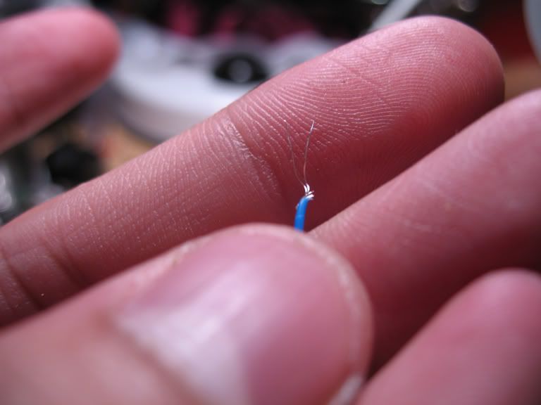
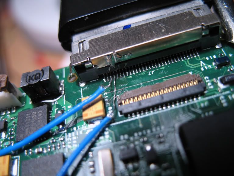
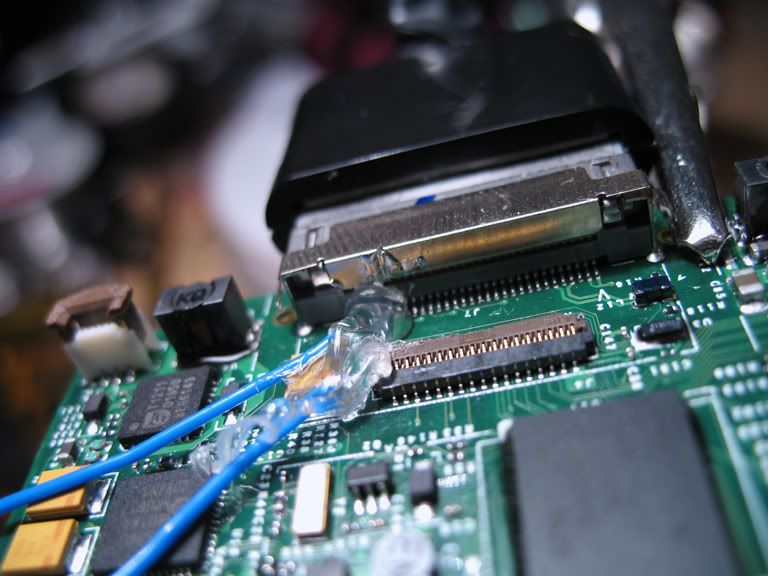
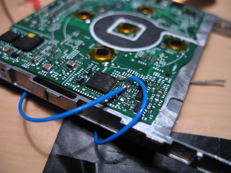
Here is an alternate method of connecting the chip to the dock. I ripped the pads off the L2, L3 and circular pads, so I had to come up with an alternate version. I routed the wires from the chip around the metal frame to the back, right up to the dock's pins. I had to twist 2 strands from my 7 stranded SPC wire because anything more would make it touch the adjacent pins. Observe.

smallerIMG_8577.jpg


Some mighty fine work that kept me up pretty late last night.
smallerIMG_8579.jpg


Glue is an essential part of the healthy, balanced diet.
smallerIMG_8580.jpg


Yeah, those Z pads decided to up and leave the diyMod party.
smallerIMG_8582.jpg


Let the record show that this method is the 3rd resort. Try the inductor pads, then the circular pads, and if all else fails, go straight to the dock. Always remember to secure those wires.
 
Jan 10, 2008 at 8:12 PM Post #674 of 3,220
Lol jon, WOW! All I can say is: "pretty amazing"! If you can solder like that, you wont have to worry about too much in the diy field. That is about as bad as it gets! Great work! Thats very clean as well! Good job!

Thats crazy hard to do. Haha, you can see the solder on the docking port where you probably rubbed against it. What size tip did you use to accomplish this?

EDIT: Thats about as 'clean' of a signal as you going to get! Not having any trace to go through...again, great work!
 
Jan 11, 2008 at 12:08 AM Post #675 of 3,220
It's the standard tip on my Weller WLC100, the ST3. The trick is to heat up the wire enough so that the solder you use to tin it will melt onto the pin. I probably would have done the same thing with a smaller tip. And of course, I must also give credit to my Helping Hands because they helped me greatly with getting a good angle with the lighting, and of course for holding up the darn board in the first place. Great confidence builder.
 

Users who are viewing this thread

Back
Top