


joneeboi
Headphoneus Supremus
- Joined
- Jul 7, 2006
- Posts
- 1,919
- Likes
- 20
I added a spiel on the nano 2G at the bottom of the original post. Anyone with a nano 2G who can confirm or disprove my conjectures would be of great help, as I don't have one on hand.
I'll post it here to save you time

[size=medium]iPod nano 2G[/size] - untested
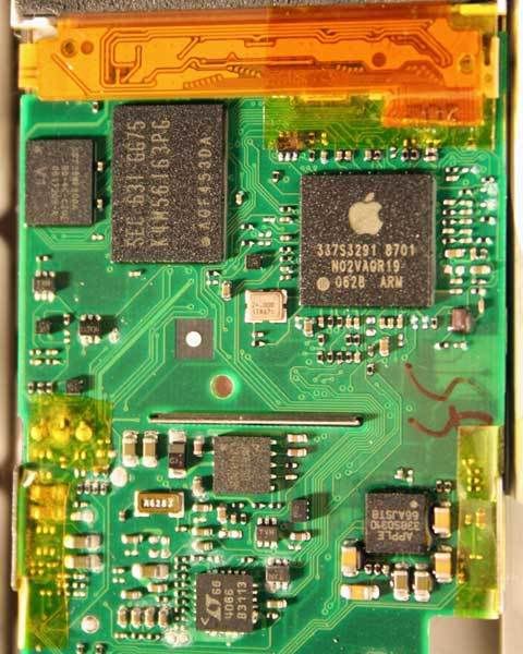
That Apple branded 66AJSTB is supposed to be similar to the Wolfson WM8750, which should be similar tot he WM8975, according to the iPodlinux site. If anyone is so daring as to slice and dice their nano 2G's beautiful finish for the education of the community, I'm sure at least one person will be grateful for your DIY spirit. If my memory serves me, the 5G's WM8758 was supposed to be similar to the WM8750 when it actually borrowed more from the WM8978. If the 66AJSTB is more like the 5G's in that it shares the pinout of the WM8978, then the pair of caps sitting at the bottom middle of the chip, the ones with the darker yellow colour than the outside pairs, might be what you're looking for. In my experience, Apple has placed the target caps side by side, a fact that helped me figure out the diyMod 5G. If this policy is true, then the left side of the chip (as shown) cannot hold the traces we're looking for. If the 66AJSTB has the same pinout as the WM8978, then that darker yellow pair of caps process the information from OUT3 and OUT4 from the WM8978 datasheet, our target line out feeds. The leftmost dark yellow cap would then be OUT4, right, and the rightmost would be OUT3, which would be the left line output.
I'll post it here to save you time
[size=medium]iPod nano 2G[/size] - untested
That Apple branded 66AJSTB is supposed to be similar to the Wolfson WM8750, which should be similar tot he WM8975, according to the iPodlinux site. If anyone is so daring as to slice and dice their nano 2G's beautiful finish for the education of the community, I'm sure at least one person will be grateful for your DIY spirit. If my memory serves me, the 5G's WM8758 was supposed to be similar to the WM8750 when it actually borrowed more from the WM8978. If the 66AJSTB is more like the 5G's in that it shares the pinout of the WM8978, then the pair of caps sitting at the bottom middle of the chip, the ones with the darker yellow colour than the outside pairs, might be what you're looking for. In my experience, Apple has placed the target caps side by side, a fact that helped me figure out the diyMod 5G. If this policy is true, then the left side of the chip (as shown) cannot hold the traces we're looking for. If the 66AJSTB has the same pinout as the WM8978, then that darker yellow pair of caps process the information from OUT3 and OUT4 from the WM8978 datasheet, our target line out feeds. The leftmost dark yellow cap would then be OUT4, right, and the rightmost would be OUT3, which would be the left line output.


