SOHA II - Super SE Hybrid
Jul 10, 2008 at 8:15 AM Post #121 of 707
Quote:

Originally Posted by runeight /img/forum/go_quote.gif
..........SOHA II uses the acronym just to keep the lineage of low voltage hybrid. The amp is a natural successor to the SOHA........


Yes, that makes sense to me now.

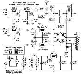
runeight, Alex, your designs are terrific and to me at least always have hidden depths, such as the use of the centre tapped transformer in the power supplies.

This one is fascinating too. Low voltage mains amps are indeed a great way for the likes of me to get introduced to tubes, and having you to explain the issues and design decisions really helps alot.
smily_headphones1.gif
 
Jul 10, 2008 at 4:57 PM Post #122 of 707
The case can be used for EI or Toroidal types. I have used it for a toroidal type before.

I am not sure the case will fit the toroid for the SOHA II, however. As I said, I have used that case in the past for an Avel Lindberg 15VA toroid for a CK2III. The SOHA II requires a 30VA, which is a bit bigger. The 15VA barely fit in there, had to shove it in and it bulges the sides a bit. The dimensions on Jameco's site is the external case dimensions, and the case is slightly sloped/angled.
 
Jul 11, 2008 at 12:28 AM Post #123 of 707
Quote:

Originally Posted by holland /img/forum/go_quote.gif
The SOHA II requires a 30VA, which is a bit bigger. The 15VA barely fit in there, had to shove it in and it bulges the sides a bit. The dimensions on Jameco's site is the external case dimensions, and the case is slightly sloped/angled.


30VA? When runeight said 15-0-15/1A I just assumed that it was 1A total current secondary, rather than per-winding. If it is indeed the larger toroid, that makes it a bit more difficult!
 
Jul 11, 2008 at 3:21 AM Post #125 of 707
Sorry for any confusion gentlemen. Daveze is correct. Two transformers that will work are:

Avel Lindberg Y236103 and Hammond 182J15. There are surely others too.
 
Jul 11, 2008 at 4:56 PM Post #127 of 707
onform, JeffR has just submitted the prototype board order. Should be about a week before he gets boards and then a little time to ship them to the prototype team. After that, I guess they will all post pics as they make progress and have something to show.

Also, when the prototype boards arrive at Glass Jar I will make the new website available. There will be lots of info there. But it will not be complete while we wait in feedback from the prototype team.

Hang on . . .
 
Jul 13, 2008 at 2:00 AM Post #128 of 707
Quote:

Originally Posted by dBel84 /img/forum/go_quote.gif
......... I have a few more scribbles but reading through what I have already written, it is clearly not objective, but then when is music objective. SOHA II just passes it through to the headphones uncluttered and with great authority.

I am enjoying listening to this amp very much. It does some things extremely well, in particular its authoritative bass reproduction. It separates instruments very well, perhaps not as well as some $2K amps I have heard but it performs well above it’s commercial price point and then some. I will leave the final word for others when they have built and tested theirs.

A further word of thanks to Alex for sharing his work even after all the adversary..dB


From this initial set of listening impressions, sounds like the SOHA II has tremendous potential to be a Low-Voltage Tube-Rollers dream in the making. Certainly sounds like Runeight has licked both the Buffer instability problems along with very low DC current with this new Servo'd design to allow for output signal path Cap Free operation into Low Z Phones.

I would assume we still have a real Tweakers platform here also to roll Boutique Film caps into that signal path Interstage position, try out different BJT's in the Output Buffer position, along with opputunity to try out some signal path resistor changes especially with that Final Buff output stage. That is, assuming that you ever get tired of rolling triode pairs...
tongue.gif


By the way - can you offer any details on the interstage cap (it appears to be a lowly Dayton film cap) used for the prototype?
Also, appears that near commecial quality Xicon Caps were used for the Elytics! Following true to the SOHA low cost build approach.

Quote:

Originally Posted by runeight /img/forum/go_quote.gif
onform, JeffR has just submitted the prototype board order. Should be about a week before he gets boards and then a little time to ship them to the prototype team. After that, I guess they will all post pics as they make progress and have something to show.

Also, when the prototype boards arrive at Glass Jar I will make the new website available. There will be lots of info there. But it will not be complete while we wait in feedback from the prototype team.

Hang on . . .


Hang on...? From the initial listening impressions I am left drooling. Glad to hear this is moving forward into a full group proto stage.
wink.gif


Closer and closer...
cool.gif
......he slowly moves unnoticed by those around him torwards the early queing line at the soon to be announced GB site
cool.gif
LoL

Any further details to offer on your Power Supply topology to link with this Amp design. I would assume with the lower PSRR of the tube stage we have a little more sophisticated lower ripple circuit on tap?
 
Jul 13, 2008 at 2:34 AM Post #129 of 707
Thanks for the post 04BluMach. I'm kind of waiting myself since I'll be one of the prototypers.
smily_headphones1.gif


dBel84 did use the Dayton caps for his proto. But the actual stock cap is a 220n Wima (or similar) box film cap. The board is very tight. It will be hard to sub other caps into the interstage slot when the board is used in the Hammond enclosure. There is another set of pads for a different pitch cap, but not much room for anything else.

So, cap rolling will require an enclosure where you create a bit more room for the larger caps, probably on the bottom of the board.

Most of the caps are spec'd from Xicon sizes, but there are a few multiple pad sets on the electrolytics so that you can use Nichicons and others.

You're right the PS is a bit more sophisticated than the SOHA for the reasons you guessed. Slightly lower PSRR of the mirror demands lower ripple from the B+.

I think you guys will like the PS. Coming soon.
 
Jul 20, 2008 at 1:44 AM Post #131 of 707
Proto boards have been shipped and are scheduled to arrive at Glass Jar on Wed of this week.

Prototypers are busy collecting their parts while waiting for the boards to arrive.

Making progress . . .
 
Jul 20, 2008 at 8:06 PM Post #132 of 707
A few posts back I promised to post the SOHA II PS. Here it is.

The LV supply is a typical IC regulated split supply from a full wave bridge on the 15-0-15 secondary. There is nothing much new here. But it is a simple, dependable supply for this amp and its large, high current SE buffers. Remember that both buffers will consume 200mA of idle current.

The Heater supply is similar to the SOHA. It uses a full wave rectifier wired to generate a negative supply of -12.6V. The resistor R3P is there to consume some of the power that would otherwise have to be burnt in the regulator, reducing heatsink requirments. Three LEDS are available for lighting the tubes and a panel light.

The most interesting feature of the heater supply is the jumper for swapping heater voltages. This jumper is on the board. And, as you can see, it is a simple matter of moving two jumpers to go from 12.6V to 6.3V and back. Maximum current is intended to be 300mA for both tubes. 6.3V tubes are wired in series by the jumper. 12.6V are wired in parallel. Notice that the jumper is wired exactly like a DPDT switch so you can connect a switch to the jumper pads. That way you can mount the heater switch on the front or back panel. No jumper swapping!!

The big difference between the SOHA PS and the SOHA II PS is the B+ supply. First, the voltage multiplier is independent of the LV+ supply rail. It is a stand alone multiplier that generates an B+ that is 1.5X the full voltage of the secondary. This would be 1.5 * 1.414 * 30 = ~63V.

The filter section must have better ripple rejection than the SOHA so it uses a series of cap multipliers to maximize ripple rejection while minimizing the voltage drop in the filter section. The goal is to get 60V B+.

The cap multipliers are not regulators, however, so I decided to separate the B+ outputs for the channels to minimize crosstalk through the plate supply.

Like the SOHA, everything runs from a single transformer.
wink.gif


That's about folks. I'll release the full SOHA II website in a day or two. But this should give you something else to look at for a while.
smily_headphones1.gif


SOHAIIPS.gif
 
Jul 21, 2008 at 4:36 PM Post #135 of 707
Quote:

Originally Posted by runeight /img/forum/go_quote.gif
A few posts back I promised to post the SOHA II PS. Here it is.


Thanks for follow up! Definitely building on the SOHA improvements you made on the initial design and a lot of improvements brought to bear for the II.

Quote:

Originally Posted by runeight /img/forum/go_quote.gif
The Heater supply is similar to the SOHA. It uses a full wave rectifier wired to generate a negative supply of -12.6V. The resistor R3P is there to consume some of the power that would otherwise have to be burnt in the regulator, reducing heatsink requirments. Three LEDS are available for lighting the tubes and a panel light.

The most interesting feature of the heater supply is the jumper for swapping heater voltages. This jumper is on the board. And, as you can see, it is a simple matter of moving two jumpers to go from 12.6V to 6.3V and back. Maximum current is intended to be 300mA for both tubes. 6.3V tubes are wired in series by the jumper. 12.6V are wired in parallel. Notice that the jumper is wired exactly like a DPDT switch so you can connect a switch to the jumper pads. That way you can mount the heater switch on the front or back panel. No jumper swapping!!


Designed in switchable heater voltages for flexibilty of tube selection is a great touch and a touch elegant in the approach. Very Nice!

Quote:

Originally Posted by runeight /img/forum/go_quote.gif
The most interesting feature of the heater supply is the jumper for swapping heater voltages. This jumper is on the board. And, as you can see, it is a simple matter of moving two jumpers to go from 12.6V to 6.3V and back. Maximum current is intended to be 300mA for both tubes. 6.3V tubes are wired in series by the jumper. 12.6V are wired in parallel. Notice that the jumper is wired exactly like a DPDT switch so you can connect a switch to the jumper pads. That way you can mount the heater switch on the front or back panel. No jumper swapping!!

The big difference between the SOHA PS and the SOHA II PS is the B+ supply. First, the voltage multiplier is independent of the LV+ supply rail. It is a stand alone multiplier that generates an B+ that is 1.5X the full voltage of the secondary. This would be 1.5 * 1.414 * 30 = ~63V.

The filter section must have better ripple rejection than the SOHA so it uses a series of cap multipliers to maximize ripple rejection while minimizing the voltage drop in the filter section. The goal is to get 60V B+.

The cap multipliers are not regulators, however, so I decided to separate the B+ outputs for the channels to minimize crosstalk through the plate supply.


The voltage regulator approach for the B+ certainly simplifies the LRC filtering that would be needed to come close to its equivalent ripple reduction and voltage regulation.

The Quasi Dual Mono B+ is a great approach to solving potential channel crosstalk and provides double voltage regulation for the HV delivery to boot.

The PS certainly looks like a great building block for delivering high end performance in the SOHA II.

Like prior poster said - Thanks for another great explanation runeight!

...........Bring it on
icon10.gif
 

Users who are viewing this thread

Back
Top