SOHA II - Super SE Hybrid
Sep 21, 2008 at 5:40 PM Post #391 of 707
Quote:

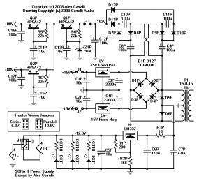
Gewa, it's already there. The HV regulator (TO-220 device) is located at the lower left corner.
wink.gif


Quote:

Gewa, the website has been updated for a few days now, including new images, new schematics, and new parts lists. Have you looked?


I did look but apparently not good enough, even updated my personal BOM according to the changes. I told you I was still in holiday mode [size=xx-small]([/size][size=xx-small]feel like an ass now
redface.gif
)

[/size]Ah well, at least I'm a 100+ Head-Fi'er now
smily_headphones1.gif


Regards
 
Sep 21, 2008 at 5:43 PM Post #392 of 707
Gewa, I hope this hasn't changed your BoM too much. I know that you've already got the parts for the original.

I think you should stay in holiday mode. As long as you can.
biggrin.gif
 
Sep 21, 2008 at 5:45 PM Post #393 of 707
Man, I've been offline from this for a bit. Havent finished my prototype build yet
frown.gif
Got stuck on some voltage issue. Time to get back on the horse
smily_headphones1.gif
 
Sep 22, 2008 at 2:52 AM Post #395 of 707
Nice, kklee. I'm doing mine on perfboard right now and it's going so slow (lack of motivation), and I removed all the old HV as well. I'm going to feed mine into D9P/D10P and use the old HV cap I have there. It seems you did something similar, but put a terminal block on the old cap position. Good idea as well.

Nice PCB. I wish I did that now. :p
 
Sep 22, 2008 at 5:28 PM Post #396 of 707
Quote:

Originally Posted by kklee /img/forum/go_quote.gif
Got my amp running with the new HV circuit via a DIY PCB. I removed all of the parts for the old HV circuit from the board.


kklee, have you made your own PCB for the HV B+ PS?
Well done!
smily_headphones1.gif
 
Sep 22, 2008 at 7:59 PM Post #397 of 707
Quote:

Originally Posted by Ferrari /img/forum/go_quote.gif
kklee, have you made your own PCB for the HV B+ PS?
Well done!
smily_headphones1.gif


Thanks!

I can make one for anybody else from the prototyping team that wants one. The only issue you may have is whether there is enough space for it. The PCB isn't that small since it was the first time I ever made a PCB using toner transfer and wasn't sure how tight I could get the traces. I have a fair amount of space in my amp chassis so it worked out perfectly.
 
Sep 22, 2008 at 8:11 PM Post #398 of 707
Quote:

Originally Posted by kklee /img/forum/go_quote.gif
... The only issue you may have is whether there is enough space for it...


It's about half the size of the one I perfboarded!
regular_smile .gif
Have you had a chance to do any A/B testing yet? I currently only have one amp - plan is to build up the other after I return from vacation next week...
 
Sep 22, 2008 at 8:57 PM Post #399 of 707
Quote:

Originally Posted by wiatrob /img/forum/go_quote.gif
It's about half the size of the one I perfboarded!
regular_smile .gif
Have you had a chance to do any A/B testing yet? I currently only have one amp - plan is to build up the other after I return from vacation next week...


The A/B testing will have to wait until next week when I go back to work (the other amp's at the office). It's sounding pretty good so far at 90V.
 
Sep 22, 2008 at 9:43 PM Post #400 of 707
My perfboard, or PC board rather, looks to be about the same size as kklee's. There's some space that can be compacted further. I'm using the smallest Ratshack PC board, about 1.85x2.85.

I made a small mistake and put a diode in the wrong direction. I've never seen a lytic blow up before, but it was interesting. Kind of like a geyser, quite impressive.

I think my diving under the table was probably more interesting. It blew up right under my nose, as I was probing around....I think I'll start wearing eye protection.
 
Sep 23, 2008 at 1:05 AM Post #401 of 707
Quote:

Originally Posted by holland /img/forum/go_quote.gif
... It blew up right under my nose, as I was probing around....I think I'll start wearing eye protection.


Being a bit of a noob - I've been putting on the safety glasses when working with my perfboarded HV supplies - Facial scars build character - but I could do without the glass eye!

Given the amount of transistors I've blown up on this project (4 MPS42s - glad we took the first cap multiplier out of the circuit!) it's awonder nothing else has gone poof!
darthsmile.gif
 
Sep 23, 2008 at 2:23 AM Post #402 of 707
Quote:

Originally Posted by holland /img/forum/go_quote.gif
I think my diving under the table was probably more interesting. It blew up right under my nose, as I was probing around....I think I'll start wearing eye protection.


Good idea. CW voltage multipliers are one of the ways we physicists get zillions of volts for our crazy experiments. I am always wary around them because I've been around ones that generated 60KV (low current, but still dangerous). I've been hammered hand to hand by 1KV. I do not know why I am still alive, but I haven't forgotten the feel of that.

We are at the low end of the voltage scale where the voltages begin to get dangerous. I guess I'd like to remind all of the new builders that 100V is nothing to trifle with. But, build the amp right and the multiplier should be tucked safely away inside the box. And you'll be running the tubes closer to where they want to be.
smily_headphones1.gif
 
Sep 23, 2008 at 3:08 AM Post #403 of 707
Here are some photos of the prototype panels. I messed up the mounting holes in the corners and I had to countersink them with a drill bit. They are a bit ugly but won't be on a production panel. I've fixed the hole size and the countersink on the FPE drawings.

Knob needs to be natural aluminum, but I had this black lying around. Parts on the back panel are from the prototype BoM except for the jacks which I stole from a preamp that has been out of service forever.

Everything fits. Furthermore, the amp is dead quiet when fully cased and grounded. Now I need to make the top. And this prototype is one for the books.
smily_headphones1.gif


Users who are viewing this thread

Back
Top