Roll Call: Who's building, built, or thinking of building a beta22?
Jul 2, 2009 at 3:38 AM Post #1,141 of 3,218
Yep, but why not just recable your headphones to 4-pin xlr?
wink.gif
 
Jul 2, 2009 at 3:46 AM Post #1,142 of 3,218
Quote:

Originally Posted by DoYouRight /img/forum/go_quote.gif
Would the TRS short issue be nullified if I made a 4 pin xlr adapter to 1/4 and plugged the 4 pin side to the B22 and the female end 1/4 to my SE headphones?


Yes, but only if you only plug/unplug the XLR side. If you plug/unplug the TRS side then the same problem would still exist.
 
Jul 4, 2009 at 12:44 AM Post #1,143 of 3,218
For those that were interested in a little more information on my Beta build I've attached the files. Due to the forum attachment size limit I've had to split them up.

What IS included:
Schematics for the Beta22 control board and Sigma22 control board.
Source code for the picaxe controllers I used.
FPE designs for the front panels I used
List of parts I used for the case and where I got them from (I think I have them all in there).

What ISN'T included:
The board layouts. Couple of reasons, the boards that you see in my photos of the completed build aren't the original boards I got made, they've been modified - the schematics have been updated appropriately. Also the layout for the Beta22 board is too large to be edited in the Light version of Cadsoft Eagle.
Source code for the Volumite chip - its not mine and I don't have it.

Software you will need:
Cadsoft Eagle : Probably the best schematic drawing package I've come across for its price (Free!). There is a Lite (Free) version which is usable for most things, it does have restrictions however:
The useable board area is limited to 100*x*80*mm (4*x*3.2*inches). Only two signal layers can be used (Top and Bottom).The schematic editor can only create one sheet.
CadSoft Online: EAGLE Layout Editor
Which I later had made at BatchPCB - Home

Picaxe Programming Editor : if you are going to learn about picaxe microcontrollers then you will need this. However I would probably recommend getting a picaxe starter kit.
PICAXE

Front Panel Express Designer : Fairly simple. Just remember MEASURE EVERYTHING. I didn't measure my volume knob properly, and when the panel came I found it didn't fit in the recess. All because I *thought* I knew how large it was. (god that was a lot of innuendo...)
Front Panel Express, LLC > Front Panel Service for North America

If you want to get your own circuit boards made, here is some light reading
smily_headphones1.gif
This is where I got all my information from on how to make my boards.
SparkFun Electronics
How-to: Prepare your Eagle designs for manufacture - Hack a Day

Heres the list of parts for those just interested in that:
2x Par Metal Series 20 12"x12"x4" Black (Par Metal - 20-12124B)
1x MPI002/TERM/BL Bulgin Ring Illuminated Blue (Farnell - 430-3088)
2x MPI002/TERM/D5 Bulgin Ring Illuminated Blue/Green (Farnell - 145-4954)
1x 1.4" Goldpoint knob custom machined aluminium (Goldpoint eBay Store)
2x NCJ9FI-S Neutrik 3pin XLR-TSR socket (Farnell - 500-8396)
1x NC4FD-LX-B Neutrik 4pin XLR socket (Farnell - 139-0122)
2x NLT8FX-BAG Neutrik Speakon 8pin socket (Farnell - 999-1964)
2x NLT8MP-BAG Neutrik Speakon 8pin plug (Farnell - 999-1980)
1x Evergreen Goldsnake speaker binding posts (VT4C - SPC-02B)
1x Solid State Relay (Jaycar - SY4084 - Hongfa JGX-1505FB)
2x "Conrad" heatsinks (Jaycar - HH8550, Altronics - H0535)
1x PCB mount toroid transformer 2x 7.5V, 10VA (Altronics - M4315)
8x HiFi feet (Jaycar - HP0834)

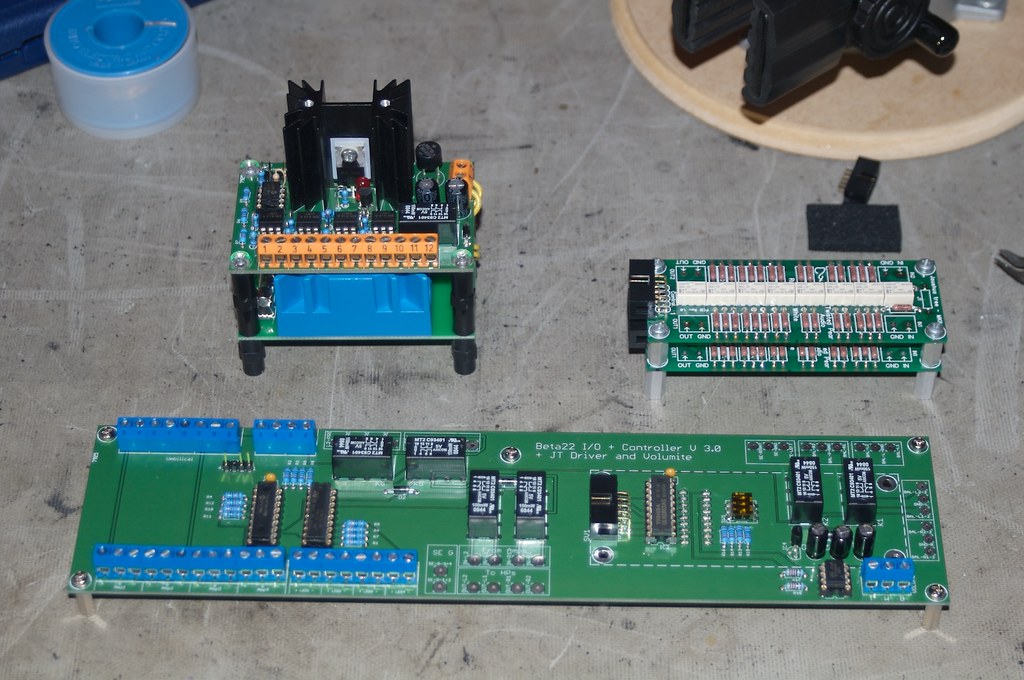
Oh, and finally a better photo of the Beta control board:
3541762706_ce20aafda6_b.jpg

Phew!


Jul 4, 2009 at 12:55 AM Post #1,145 of 3,218
wow great way to introduce your own board! would you happen to have a spare?
 
Jul 4, 2009 at 6:17 AM Post #1,147 of 3,218
Gatsu,
looks brill, and thanks for the tutorial!
 
Jul 4, 2009 at 6:34 AM Post #1,148 of 3,218
Quote:

Originally Posted by amb /img/forum/go_quote.gif
Just to remind you that it's not D12 that you need to replace, it's Q26.


Amb - I replaced Q26... twice... and I'm still getting 29 volts across D12. Any suggestions for next steps? Thanks!
 
Jul 4, 2009 at 9:53 AM Post #1,149 of 3,218
oneplustwo, try reflowing the solder joints at CR8, and make sure there is no solder bridge or a short across C10. Also make sure neither of these are mounted in the wrong direction.
 
Jul 4, 2009 at 5:13 PM Post #1,150 of 3,218
That did the trick! Had a cold CR8 joint apparently. Now I have 4 working boards! Time to finish up wiring and case work! (Still have to fix the second Sigma though... need to replace at least Q4/Q5 I think.)
 
Jul 4, 2009 at 8:34 PM Post #1,152 of 3,218
Sorryto hear about that, smeggy. Things don't just burn up without a reason. Can you visually identify any obviously burnt parts? If so which is it? Is there a short circuit in there somewhere (marginal wiring, solder joints, or loose bits? Also, you said you wired in a switch for headphones/speakers selection. Did you completely undo all the previous wiring to the switching headphone jack? I never trust using the switch on the jacks for this purpose, because the switch is activated by the plug, and on most such jacks could also cause an additional point of momentary short circuit as you plug and unplug the headphones. Also make sure you got the extra switch wired correctly.
 
Jul 4, 2009 at 8:59 PM Post #1,153 of 3,218
It's a new switch, new jack, new wiring, new ground layout, new zobel and it's been running fine for a week with no problems functionally as far as the boards go.

I turned it on and pop, nothing visually stood out. It's still making sound like you get from a partially blown driver. The sinks are cold but if you turn it up you can still get sound out but it's very distorted.

I appreciate your concern but I'm past the point where I want to sink any more time, money or effort into what seems like a lost cause, for me anyway.
 
Jul 4, 2009 at 9:27 PM Post #1,154 of 3,218
Quote:

Originally Posted by smeggy /img/forum/go_quote.gif
It's a new switch, new jack, new wiring, new ground layout, new zobel and it's been running fine for a week with no problems functionally as far as the boards go.

I turned it on and pop, nothing visually stood out. It's still making sound like you get from a partially blown driver. The sinks are cold but if you turn it up you can still get sound out but it's very distorted.

I appreciate your concern but I'm past the point where I want to sink any more time, money or effort into what seems like a lost cause, for me anyway.


Smeggy, I’m really sorry to hear about your amp. My advice is to take a breather get some fresh air, leave it alone for a couple of days. I don’t think you should give up, it’s all a learning process - even though at the moment it’s as frustrating as hell there is a positive.
You don’t want to have that amp lying around reminding you that it beat you, so snap out of it. Pick up you DDM and give that sucker what for. You can do it mate.
 

Users who are viewing this thread

Back
Top