[REVIEW] OTOMATSU DIY Portable Headphone.. AMP-X
Nov 9, 2012 at 2:51 PM Post #16 of 24
Here you go.
Jumped output resistor. Underneath because I just used the lead from where I added the bypass cap:

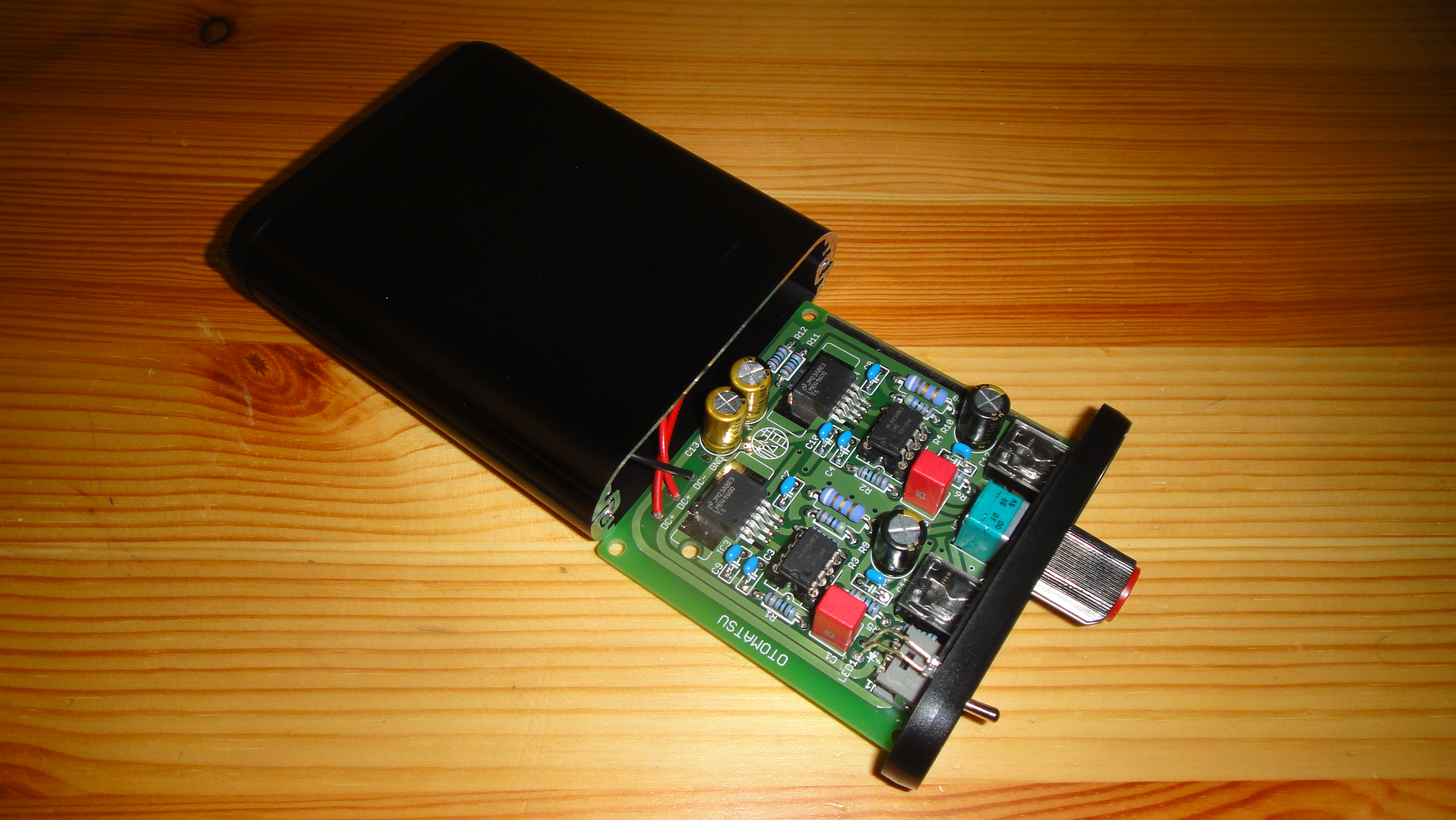
Here's the top with those added caps and replaced input caps plus the strain reliefs. I prefer this to just running the wires through the hole as any movement can break a wire joint in time.:

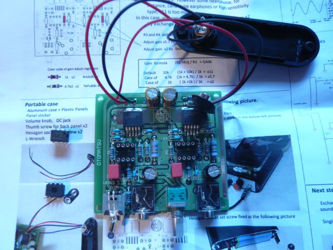
Here it is ready for a dual battery try. Moved the black lead over a spot to true ground and attached the other side across the neg phase of the supply. The resistors across the batteries shouldn't hurt performance and will stay for now. The on/off switch would need to be reworked and resistors removed if it was to be used this way:

Haven't listen yet with the stiffer 2 battery config. My batteries aren't with me.
 
Nov 9, 2012 at 10:15 PM Post #17 of 24
[size=10pt]MP-X is [/size][size=10pt]designed for[/size][size=10pt] +/- voltage [/size][size=10pt]([/size][size=10pt]this is written in the manual.[/size][size=10pt])[/size]
 
[size=10pt]Using [/size][size=10pt]double +9/-9V batter[/size][size=10pt]ies[/size][size=10pt] will significantly improve all audio performance[/size][size=10pt]s[/size][size=10pt].[/size]
[size=10pt]S[/size][size=10pt]ome Japanese DIY [/size][size=10pt]fans[/size][size=10pt] have [/size][size=10pt]already [/size][size=10pt]done this [/size][size=10pt]modification[/size][size=10pt] themselves.[/size]
 
[size=10pt]AMP-X is[/size][size=10pt] an[/size][size=10pt] open platform [/size][size=10pt]to allow you to conduct your own modifications.[/size]
 
[size=10pt]If [/size][size=10pt]performance is [/size][size=10pt]your[/size][size=10pt] priority[/size][size=10pt],[/size][size=10pt] th[/size][size=10pt]e[/size][size=10pt]n [/size][size=10pt]go for double batteries.  [/size]


[size=10pt]There are 2 interesting Japanese links about the modifications of AMP-X . [/size]
 
[size=10pt][size=10pt]http://mark-create.cocolog-nifty.com/blog/2011/10/post-0906.html[/size][/size]
 
[size=10pt][size=10pt]http://slow-tube-cresent.blogspot.jp/search/label/AMP%20%28%20OTOMATSU%20%29[/size][/size]
 
 
[size=10pt] [/size]
 
Nov 10, 2012 at 8:48 AM Post #18 of 24
I'll check the manual which I haven't looked at for a while to see what's said. I don't think the power switch is wired for independant rails but I'll check. What's happening in my pic is not just more voltage. The 2 batteries are connected directly to ground and not floating across the resistor voltage splitter circuit so it's not just more voltage I'm after but a stiffer and better balanced supply. Doesn't look like those links are doing it like this. Just checked, the manual doesn't address it as independant rails and the power switch would need to be replaced to configure it that way. Also, as you change the voltage the splitter will be become less balanced. Generally not a big issue as long as there's enough on a leg.
 
 I personally think the basics like a stiffer supply and lower output impedance are more important than a fancy chassis or different opamps though there's nothing wrong with that either.
bigsmile_face.gif
I also don't like the idea of not having an input coupling cap as one of those links has done. I would instead keep that one and once I knew my supply would stay balanced, work on the resistor values to lower the output DC which is already not bad. Removing the output cap and resistor should be a better mod than removing the input DC blocking cap though nothing basically wrong with either. Here's where a regulated dual rail supply might help even more. 
 
Looks like they have upgraded a lot of parts in those links. I like it cheap and cheerfull and used a couple things that I already had around but it's nice to know there's a lot of versatility here in terms of circuit and parts. I wouldn't mind having a slightly larger 470mF output cap for very low impedance loads but think the basic parts values and quality are quite good. It really is a nice modding platform because it has a lot of potential.
 
Nov 10, 2012 at 4:28 PM Post #19 of 24
The dual rail arrangement picks up th pace and tightens the bass, toi the point where I'd revoice the coupling caps a bit. I think some Elna Silmic II electrolytics at the output would be perfect now. I may get some 470mF and lay them over to fit and try some at the input as well before sending the amp on, if ClieOS is still interested after all the futzing about. This is a very informative amp and when tuned should garner VG results.
 
Nov 11, 2012 at 6:07 AM Post #21 of 24
Goodvibes thanks for that.  i will try doing these things when i have time and report back to you here. I iwill be straight up with you though and say i have lil knowledge on circuitary like you do so the help is appreciated. If i can get it to sound awesome that'd be great.
 
Kiteki, whats the website address?
 
Nov 11, 2012 at 10:44 AM Post #23 of 24
Quote:
Goodvibes thanks for that.  i will try doing these things when i have time and report back to you here. I iwill be straight up with you though and say i have lil knowledge on circuitary like you do so the help is appreciated. If i can get it to sound awesome that'd be great.
 
Kiteki, whats the website address?

No formal training so not nearly where you may think I'm at but some of this stuff is very straight forward once you get a feel. Right now, I'd say get some Silmic II 470mF (lay it over to fit) for the output and find something you like for the input cap. You can try another silmic there and nothing wrong with 10mF. Regardless of what you may read, polar is fine here, neg out. Silmics tend to be full sounding so having them both at the in and out may be too warm but I'll find out. That's what I mean by voicing. Most hobbiest just hate tants as coupling caps like I have at the input as last pictured so I don't always follow norms and just use my ears for voicing. Guess why they call it voicing.
wink_face.gif
 You get a feel for the character of bits with familiarity. Sometimes you discover that interfacing is as/more important than expense until you have great expense. The 2 battery thing is pretty cool but tightened it up enough to where the amp as current will be a bit etched. If built that way the current board could accomidate it if you replaced the power switch with a double pole and the current power lead holes could them be used with +, - and 2 leads to the ground hole. Remove the V splitting resistors and you're done.
 
I won't be changing opamps. What's there is VG and it's just another unneeded variable. You can chase your tail forever if you're willing to.
 
Dec 20, 2012 at 4:32 AM Post #24 of 24
goodvibes you still playing around with this or have you arrived at a satisfactory configuration of goodies?
 

Users who are viewing this thread

Back
Top