


tomb
Member of the Trade: Beezar.com
- Joined
- Mar 1, 2006
- Posts
- 10,890
- Likes
- 1,050
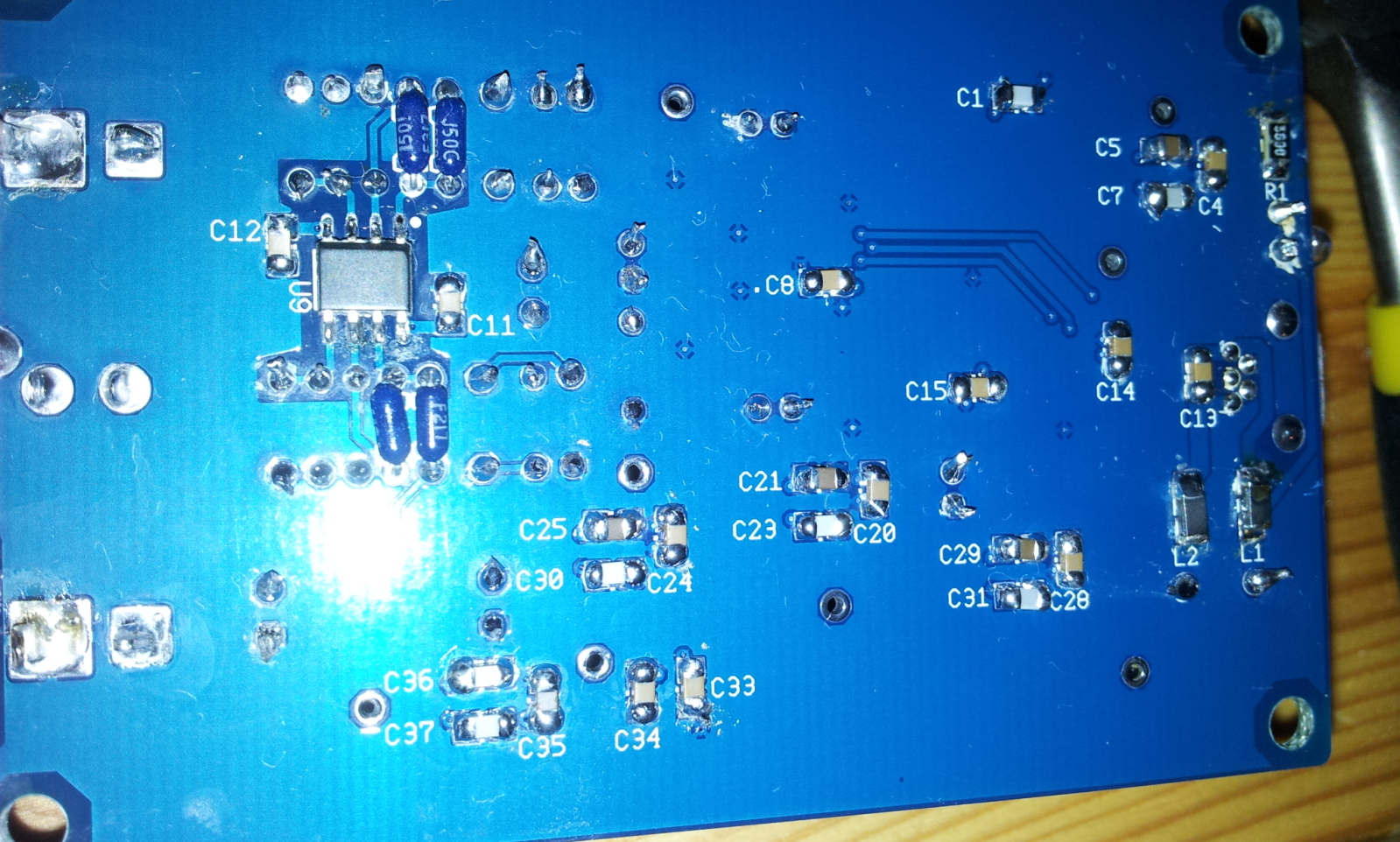
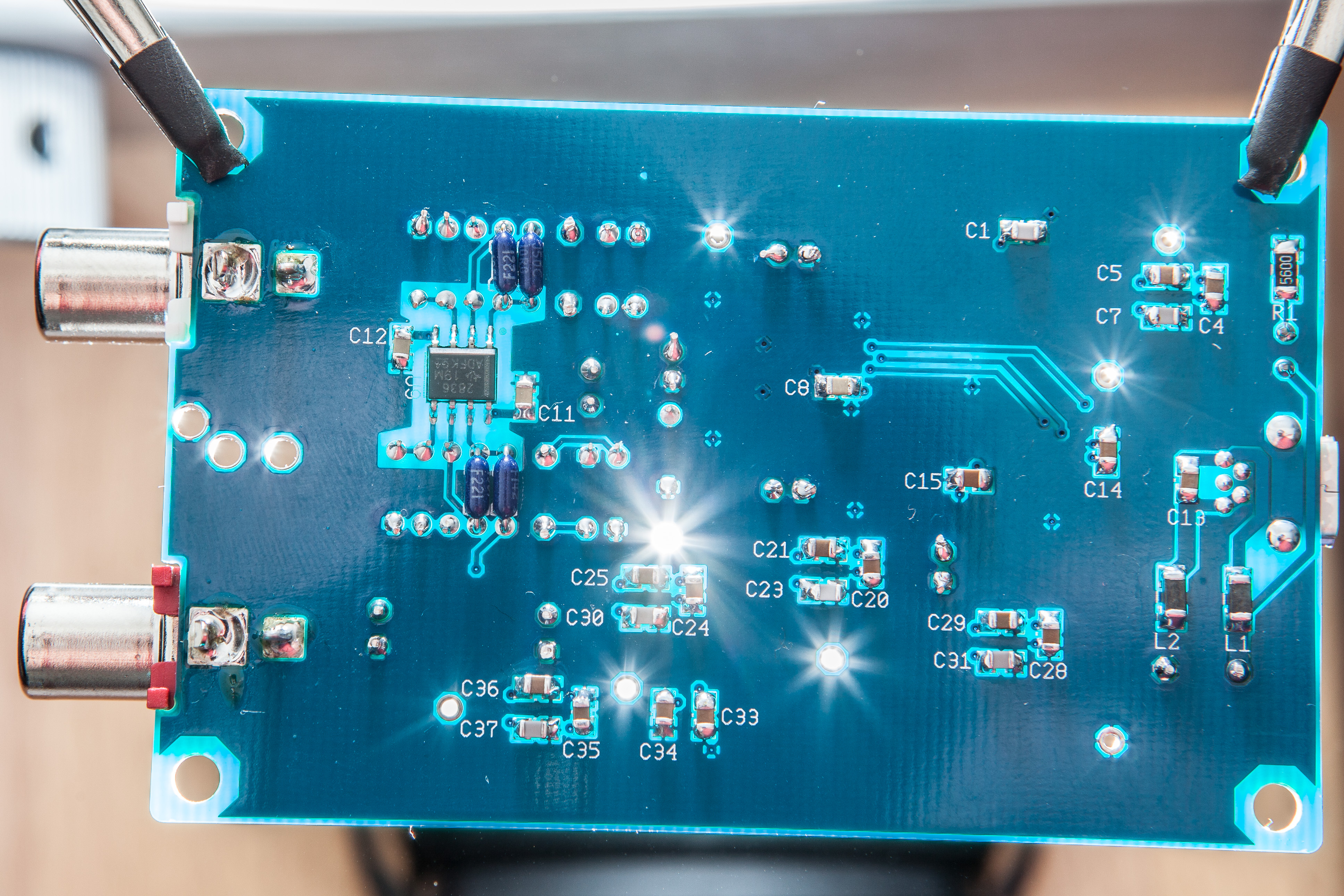
Unnecessary lead length? Are the resistors flush to the PCB. For the four you measured above, are they on the bottom of the PCB, next to the opamp? What about the mica capacitors? Those have to really be pressed into the PCB to keep from sticking way up over any other part. The added lead length could be offsetting things.
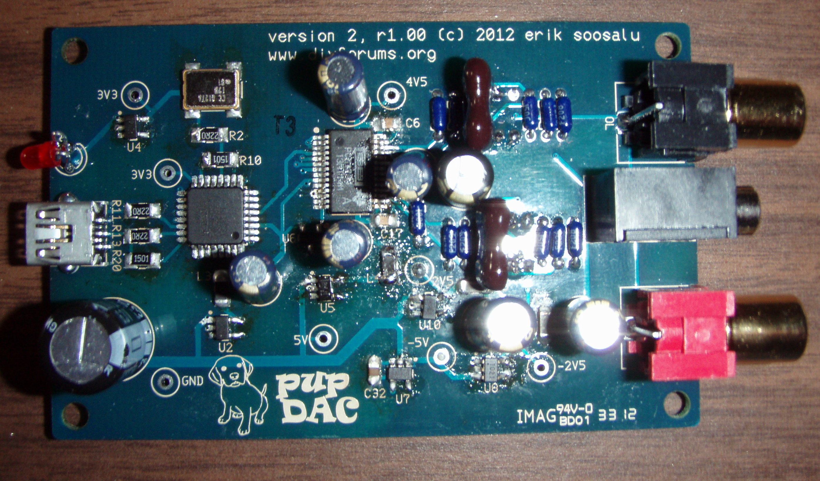
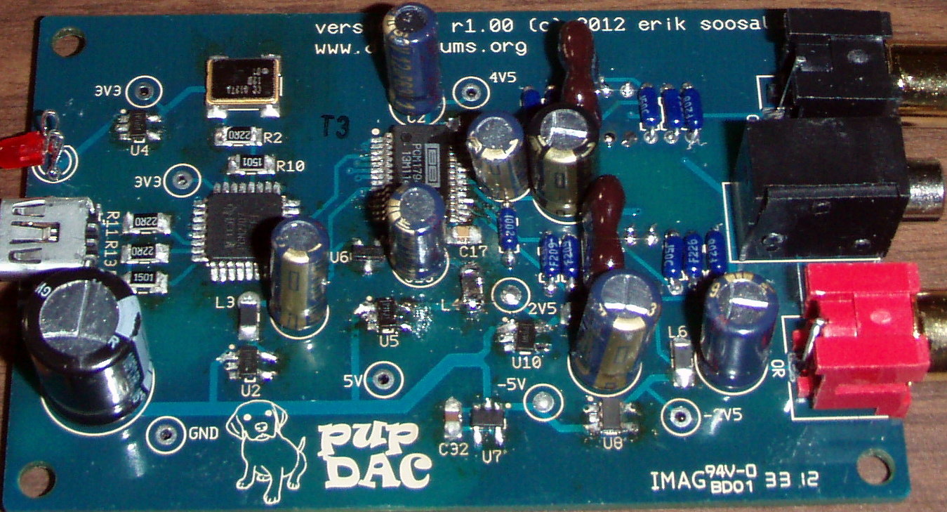
Have you tested the voltage into the opamp? These would be pins 8 and 4. See if those are the same voltage. Pin 8 should be the same as the 2.5V test point coming from U10. Pin 4 should be the -2.5V test point coming from U8. See what those voltages are at the pins on the opamp, though - relative to Ground.
I can't think of anything else. I would suggest that 3.3mV is not that much offset in the scheme of things, but you are claiming to hear a sound level difference between channels. How about the rest of the through-hole resistors? Can you compare their resistances, left channel to right channel and see if there's something not matched?
Everything is flush to the board, the mica caps do stick up maybe 1-2mm since that was as far as I could get them. Voltage into pins 4 and 8 match up.
As for the other resistors, I actually edited my last post with those readings.
Well, some of those resistors are in parallel - so the absolute values are off. Since the problem is offset, though, we'd be looking for an imbalance somewhere and you're not measuring any. The only thing left are the rest of the through-hole resistors, R5, R7 & R16, R18. Try measuring those for an imbalance.
You've checked the resistors that control the opamp and you've verified that the opamp is getting the same voltage between the channels. The only other possibility is that the signal level feeding into the opamp is off before it gets to the opamp. That would happen at the four resistors mentioned above. They take the output directly from the DAC chip (IOLP, IOLN & IORP, IORN).
If none of that checks out, I don't have an explanation.


")
