pupDAC Step-by-Step Build Thread
May 10, 2014 at 9:05 PM Post #256 of 359
<snip>
 
@COOKIESnPIE I'm all out of ideas
frown.gif

Me, too.  I greatly appreciate your effort in trying, though!
 
COOKIESnPIE,
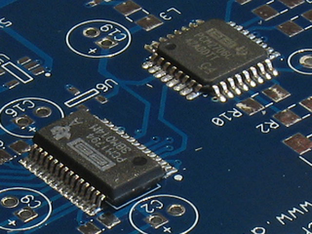
It may be as mcandmar says - one of the chips somewhere may be bad, perhaps too much heat in soldering, etc.  I confess that out of over a dozen PupDAC's I've built, there's one that baffles me - but it was one of four that I was building at the same time and I realized about midway through that I had the iron turned up way too high.  Plus, it was the first one in the lot and I spent a lot of time re-positioning the PCM chips - it turned out to be practice for the other three, but I think all that time exposed the primary chips to too much heat.  I later on replaced the PCM2707 chip, but it still doesn't work, which makes me think it has to be the DAC chip, now.  All voltages are correct and there's no offset to speak of on the output.  The PC just won't recognize it, however, and continues to give a USB connection error (why I thought it was the PCM2707 chip).
 
Anyway, I hope you can figure it out on yours.  I'm at a loss to give you any constructive guesses at this point - that's all they'd be: guesses.
 
May 10, 2014 at 9:21 PM Post #257 of 359

 
LOL, oh what fun i could have trolling the ODAC thread with that one
very_evil_smiley.gif

 
May 10, 2014 at 10:54 PM Post #260 of 359
If we do the math, assuming R3, R4,R14 and R15 (Riv) are 22 ohms and the center current of the PCM1794a is -6.2mA...

 
Actually, the resistance seen by the output of the DAC is 21.7 ohms, we will use that figure.

 
The voltage at Riv should be 134.54mV. There is a 2% tolerance giving us a range of 137.2308mV to 131.8492mV.

 
R7 and R8 form a voltage divider yielding 126.131 at the non-inverting input of the op amp.
 
This does not take into account resistor tolerances or op amp bias current/voltages.
 
May 11, 2014 at 4:42 AM Post #261 of 359
 
 
LOL, oh what fun i could have trolling the ODAC thread with that one
very_evil_smiley.gif

 
Now that is interesting
eek.gif

I've seen your results in the doodlebug thread for the PuPdac without the doodlebug.
Did you happen to run the ODAC without the doodlebug? I had made an assumption
that the ODAC might benefit from the doodlebug more than the PuPdac in a typical
setup because the ODAC seems to be light on power rail filtering at first glance. 
 
I wouldn't want to stir up a hornet's nest, but that is interesting.
 
May 11, 2014 at 11:28 AM Post #263 of 359
Perhaps the voltage being lower than expected is due to the PCM expecting to get 5 volts but
only getting 4.75 due to regulation and filtering.
 
I will measure mine and see what I get.
 
May 11, 2014 at 11:56 AM Post #264 of 359
Here are the results I got from mine.
 
Mine is a prototype version but close enough.
 
Riv
1. 127.0
2. 127.1
3. 125.3
4. 125.5
 
Offset
 
Right: 2.2mV
Left: 0.6mV
 
2835
 
1. 0.6mV
2. 119.1mV
3. 119.1mV
4. -2.49V
5. 117.1mV
6. 117.6mV
7. 2.2mV
8. 2.5V
 
May 11, 2014 at 1:25 PM Post #265 of 359
   
Now that is interesting
eek.gif

I've seen your results in the doodlebug thread for the PuPdac without the doodlebug.
Did you happen to run the ODAC without the doodlebug? I had made an assumption
that the ODAC might benefit from the doodlebug more than the PuPdac in a typical
setup because the ODAC seems to be light on power rail filtering at first glance. 
 
I wouldn't want to stir up a hornet's nest, but that is interesting.

 
I wanted to but my machine is refusing to install it, its something with Windows 8.1 as i'm having trouble getting it to install a bunch of different USB DACS.  The ODAC will only work through the Isolator in one port, and the rest of the DAC's wont work at all.   Oddly though the PupDAC will work in any port, i dont really know whats going on yet..
 
May 11, 2014 at 3:00 PM Post #268 of 359
Interesting measurements mcandmar.  You should bring up the measurements to the ODAC section.
 
Kinda off topic, but any of you guys know of a simple ESS9018 implementation like the ODAC(9023) that is powered by USB?  I want to try it, and possibly add doodlebug if the PS noise is prominent.  
 
May 11, 2014 at 6:08 PM Post #269 of 359
  I've been comparing your numbers to mine, as I'm not an engineer I can't really tell is the slight variances in our numbers make a difference.


The PCM1794a has a 2% tollerance on it's output current and all the resistors have 1% each.
I think all the voltages are within tolerance.
With all the components involved, 5% is probably not an unreasonable expectation.
If you were to match components, the best you could expect would still probably be
only about 3%.
It would be possible to add a high value resistor in parallel with Riv to trim the voltage to
closer tolerance. At least you would get your offsets down to almost nothing.


Users who are viewing this thread

Back
Top