


nini_knoxville
New Head-Fier
- Joined
- Apr 27, 2010
- Posts
- 14
- Likes
- 0
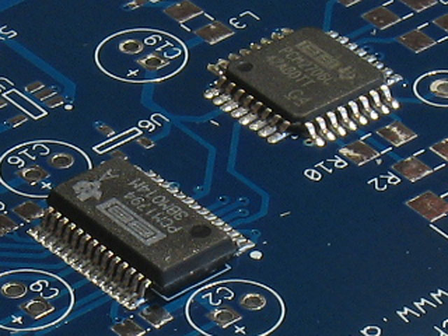
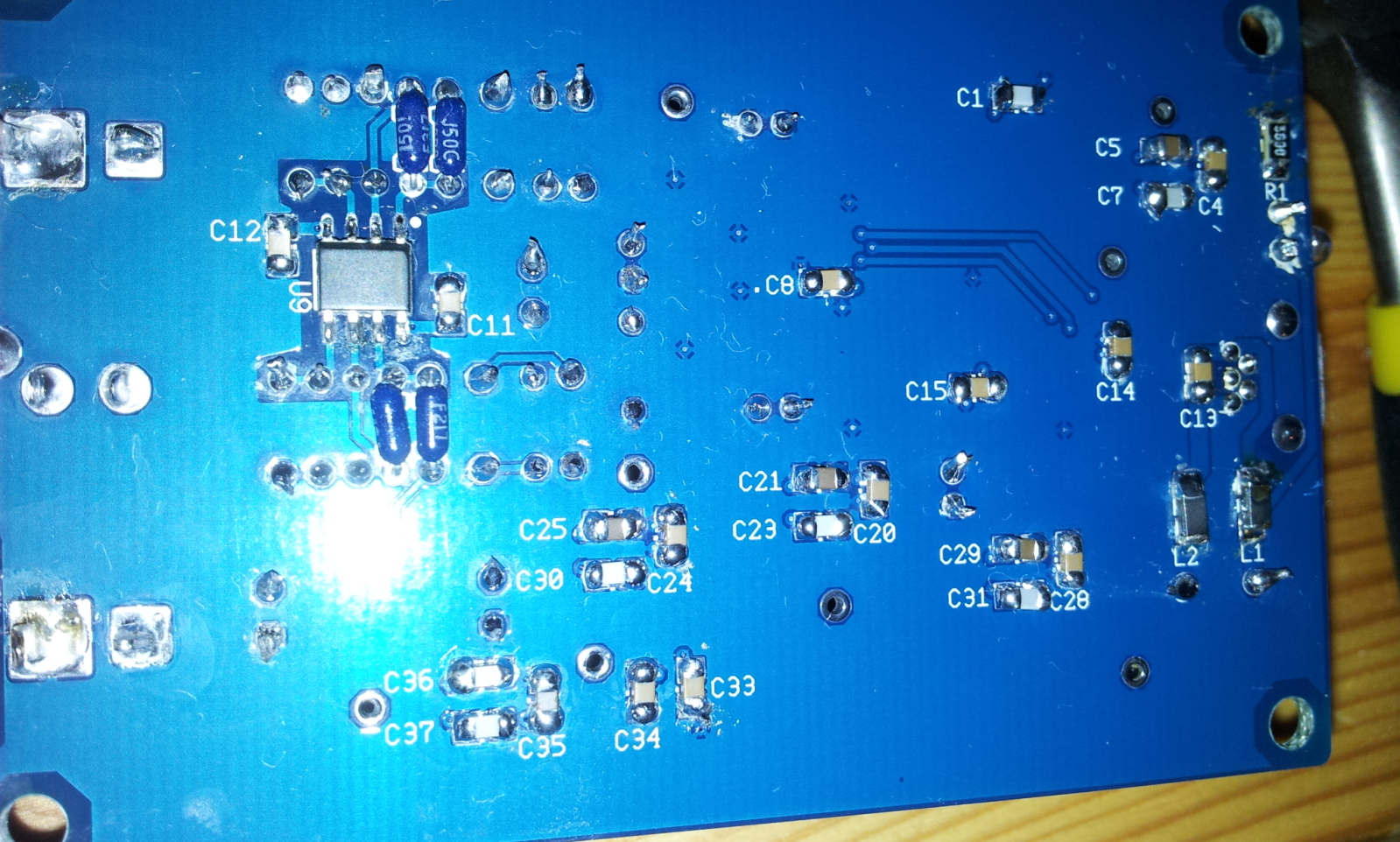
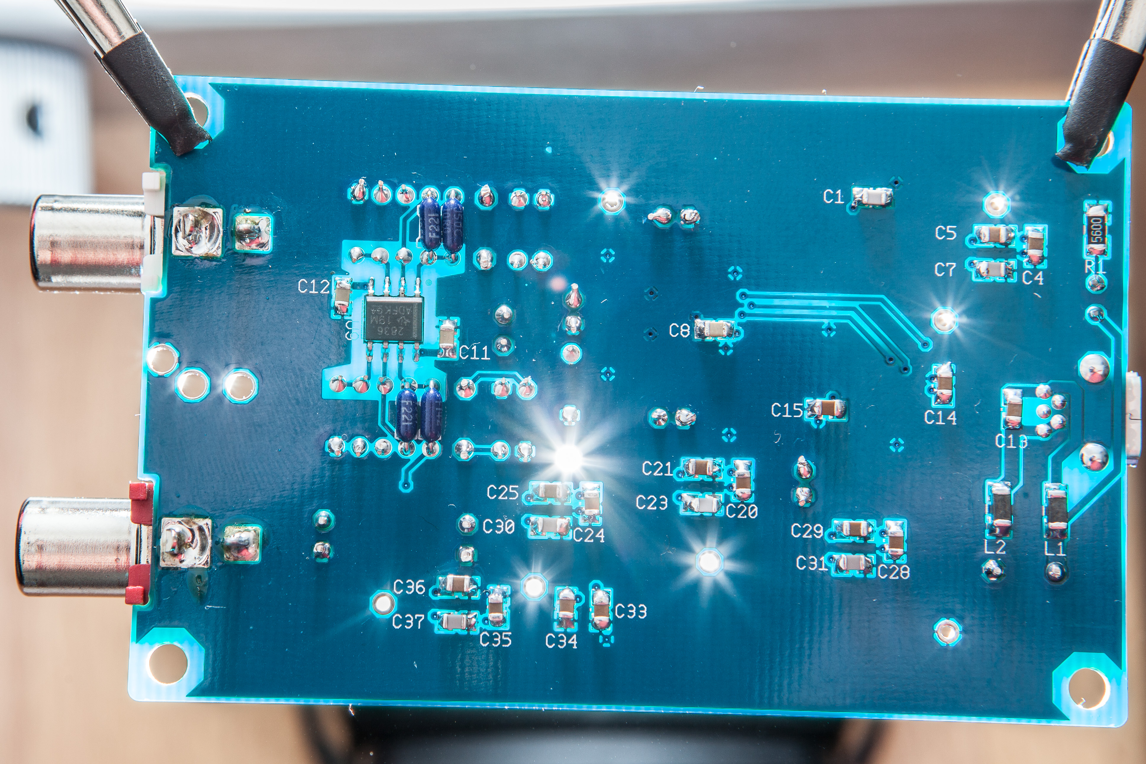
Well, for the Right channel - the 3rd and 4th pins from the bottom-right of the DAC chip are the Right channel outputs (IORN and IORP). I don't see anything wrong with those pins, but there does seem to be a "whisker" bridge starting from the 5th pin up from bottom right. I don't know if that's really something and whether it would have an effect on just the right channel, but maybe.
You've done an excellent job of soldering, especially on the two big chips. It's a reflective-photographic effect, I think, but it almost looks like some of the opamp pins are dissolved.I would not suspect the opamp at first guess, though, since it's fairly easy to solder compared to the rest of the PCB.
See if you can clear that whisker on the DAC chip and them perhaps apply a bit more heat with a few strokes of the iron on those bottom 3rd and 4th pins.
Thanks. It was my second SMD soldering kit.. the first one i did 2 weeks ago was the gamma 1/2 which suffered from a hair of a Q-Tip...
But the whisker at the DAC was doing nothing. After reapplying a little bit of solder to all of the DAC pins, the right channel stillt outputs nothing


