n_maher
Resistorous Conflagorous
- Joined
- Nov 20, 2004
- Posts
- 8,411
- Likes
- 35
I'm going to create a thread for this amp since it is my intention at the end of the build to publish the schematic and any relevant details so that anyone who's crazy enough can build this amp. As of right now the amp is in working condition and headed to Florida for the party that will be CanJam. First, a little backstory...
A Brief History of The Meance
So really this started years ago, but if I tell the story that way it won't make a bit of sense to anyone other than myself. And I did say brief history and I swear I'll try to keep it that way.
This really got going in late December of this past year when I got a message from a friend (who shall remain nameless) that they had an abandoned project that I might be interested in picking up. The basic gist of the project was that they had taken the Van Waarde project along with the Wheatfield HA-2 design and started to improve upon the general concept. Most notably this involved paralleling the output tubes and increasing the output coupling capacitance to the point where driving low-impedance headphones would be possible. The original HA-2 was technically able to do this but not all that well in my opinion. So me being the unabashed Pete Millett fan that I am and a former HA-2 owner jumped all over it. Quick note - both the Van Waarde and the HA-2 schematic are out there if you know where to look, the Waarde is at Headwize (linked above) and owners of the HA-2 know where to find its schematic. I believe that Headroom still owns the HA-2 design and as such I won't be publishing that schematic, only my revised version. Now the revised design that started this mess had been taken to the proof of concept level but in such a way that things like the power supply still needed figuring. So while I won't be using much of what was done as a part of that project I do owe my friend a huge debt of gratitude in terms of motivation and inspiration, without that initial push I'm sure that this would have never happened.
Now I'm no designer, I never have been and I never will be since there just aren't enough hours in the day and honestly I'm completely comfortable leaving that up to other folks. I love building this stuff but typically my interest dies off quickly after that point. To a degree that had to change for this project since there was still much work to be done. So I started doing some basic math along with consulting with a few folks about the power supply. It was initially my hope to simply re-use the existing HA-2 tube-rectified design and tweak it as needed. This was quickly abandoned after seeing that the existing PS design was pretty much tapped in terms of current capacity. It was at this point that I decided to call in the big guns and see if I couldn't enlist the help of the guy who was really responsible for all this. I've communicated off and on with Pete Millett for the past few years, mostly as a result of my dealings with the Low Voltage Hybrid project as well as dealing with the issues that my original HA-2 had. Like I said, I'm a hug Pete fan the guy gives tirelessly to this hobby and I can't wait to shake his hand next week, I'm getting side-tracked, back to the story. But Pete's a busy guy and I didn't really expect to have him launch into it the way that he did but it'd be safe to say that this project may well have died without his help. He continues to be a integral part of the design process and I can't say thanks enough so, thanks Pete! I started talking power supply design with Pete and we quickly came up with a couple of concepts and I elected to go with what seemed to be the simplest from a parts perspective (fewer transformers and bits that I was used to working with). I also elected to have the amplification side of the equation be essentially a tweaked HA-2 that will run parallel output tubes, larger output coupling capacitors and modified heater supplies. This should help some of the issues that the original HA-2 suffered from which were some PS hum and output impedance that wasn't really all that suited for driving Grados.
So I sketched up schematics and sent them to Pete and what followed was some back and forth that culminated with some rather large parts orders in late March but I didn't get around to actually starting the build until April 10th. Nothing like leaving myself plenty of time to get it ready for CanJam.

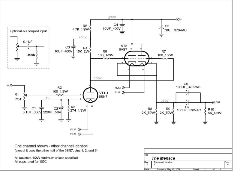
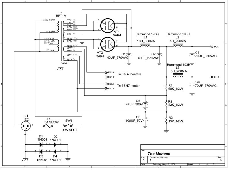
I think I'll stop here and leave the details to later on in the process but hopefully that paints at least a little bit of a picture as to where this came from and where it's headed. As I said in the beginning it's my full intention to publish the schematics that Pete and I came up with when I get back from CanJam. The versions that I have uploaded right now have a few minor errors in them and I'd rather not steer someone in the wrong direction.
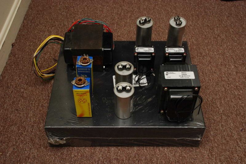
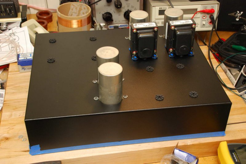
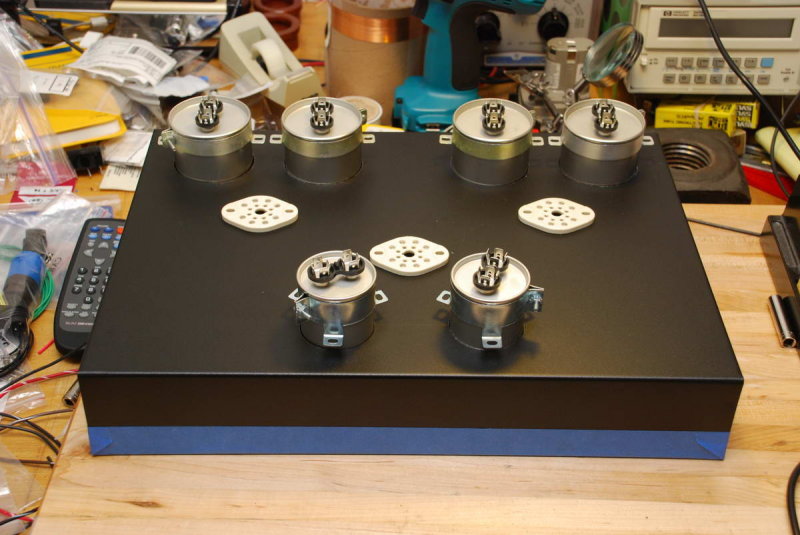
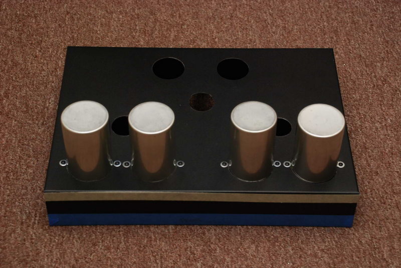
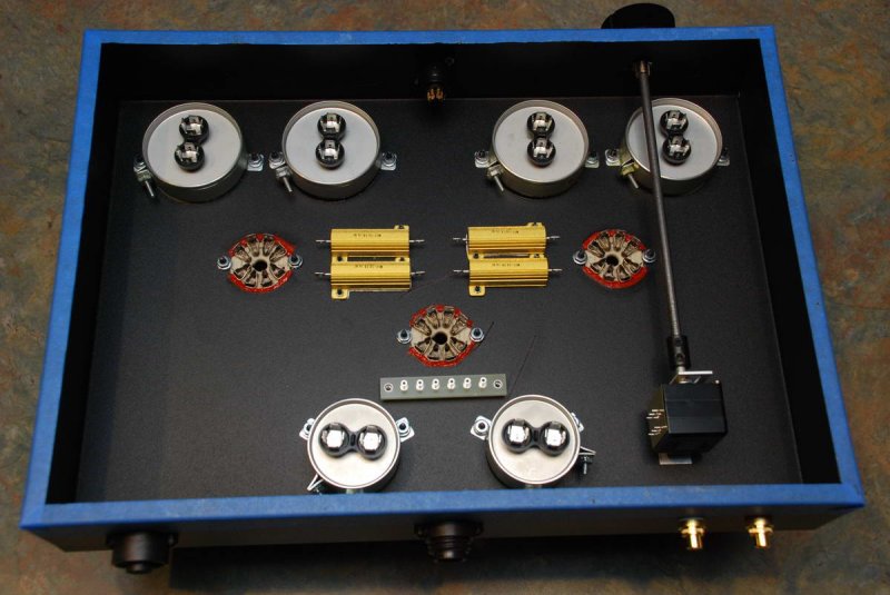
Here area a few pictures from during construction, all told I think I've got about 14 days/nights of on and off work into the amp. Maybe 40hrs or so, it's pretty hard to tell really as I'm sure if someone had large chunks of time rather than a hour here and there it could be done more quickly.
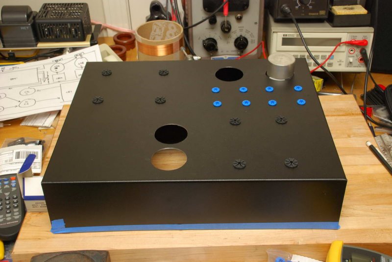
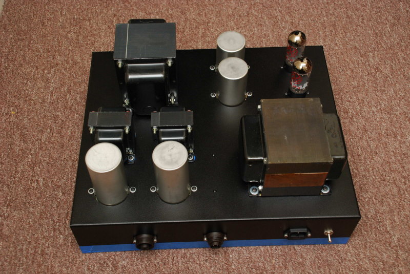
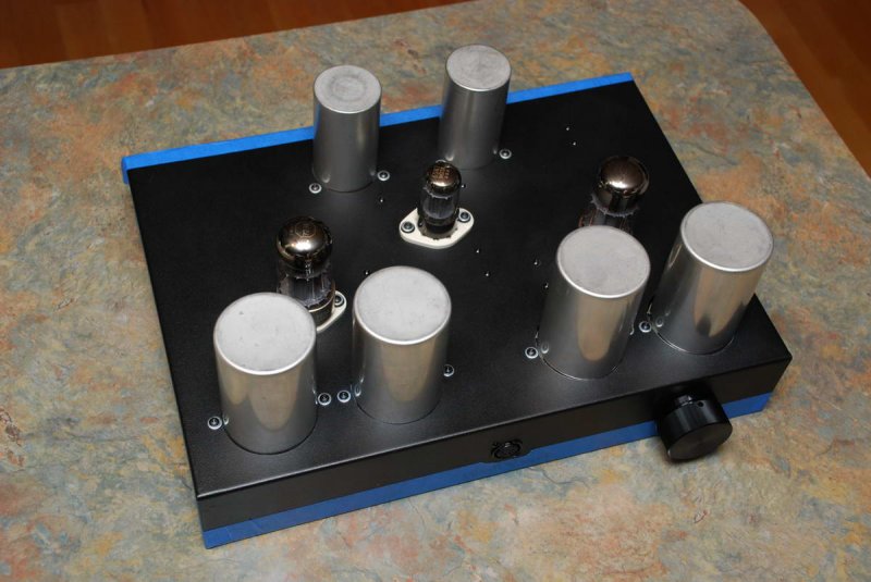
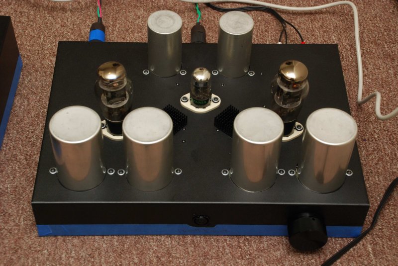
Finally, here are two shots from testing the amp last night.

I'm going to hold off on internal wiring shots until I can update pictures since there are substantial changes from what i had before. I've posted one on this site already but since this is intended to be the source for good information about the amp I don't want to cause confusion.
I also can't offer much in the way of listening impression since I've spent a grand total of 2hrs listening to the amp, only one of which was after the final modifications. What I have heard so far offers great promise and the root of the design is sound so I have little doubt that the amp will perform up to my expectations, which are quite high.

So that's it, the introduction of The Menace. Once again I have to say a huge thanks to Pete Millett who's advice and help throughout this project was simply invaluable.
A Brief History of The Meance
So really this started years ago, but if I tell the story that way it won't make a bit of sense to anyone other than myself. And I did say brief history and I swear I'll try to keep it that way.
This really got going in late December of this past year when I got a message from a friend (who shall remain nameless) that they had an abandoned project that I might be interested in picking up. The basic gist of the project was that they had taken the Van Waarde project along with the Wheatfield HA-2 design and started to improve upon the general concept. Most notably this involved paralleling the output tubes and increasing the output coupling capacitance to the point where driving low-impedance headphones would be possible. The original HA-2 was technically able to do this but not all that well in my opinion. So me being the unabashed Pete Millett fan that I am and a former HA-2 owner jumped all over it. Quick note - both the Van Waarde and the HA-2 schematic are out there if you know where to look, the Waarde is at Headwize (linked above) and owners of the HA-2 know where to find its schematic. I believe that Headroom still owns the HA-2 design and as such I won't be publishing that schematic, only my revised version. Now the revised design that started this mess had been taken to the proof of concept level but in such a way that things like the power supply still needed figuring. So while I won't be using much of what was done as a part of that project I do owe my friend a huge debt of gratitude in terms of motivation and inspiration, without that initial push I'm sure that this would have never happened.
Now I'm no designer, I never have been and I never will be since there just aren't enough hours in the day and honestly I'm completely comfortable leaving that up to other folks. I love building this stuff but typically my interest dies off quickly after that point. To a degree that had to change for this project since there was still much work to be done. So I started doing some basic math along with consulting with a few folks about the power supply. It was initially my hope to simply re-use the existing HA-2 tube-rectified design and tweak it as needed. This was quickly abandoned after seeing that the existing PS design was pretty much tapped in terms of current capacity. It was at this point that I decided to call in the big guns and see if I couldn't enlist the help of the guy who was really responsible for all this. I've communicated off and on with Pete Millett for the past few years, mostly as a result of my dealings with the Low Voltage Hybrid project as well as dealing with the issues that my original HA-2 had. Like I said, I'm a hug Pete fan the guy gives tirelessly to this hobby and I can't wait to shake his hand next week, I'm getting side-tracked, back to the story. But Pete's a busy guy and I didn't really expect to have him launch into it the way that he did but it'd be safe to say that this project may well have died without his help. He continues to be a integral part of the design process and I can't say thanks enough so, thanks Pete! I started talking power supply design with Pete and we quickly came up with a couple of concepts and I elected to go with what seemed to be the simplest from a parts perspective (fewer transformers and bits that I was used to working with). I also elected to have the amplification side of the equation be essentially a tweaked HA-2 that will run parallel output tubes, larger output coupling capacitors and modified heater supplies. This should help some of the issues that the original HA-2 suffered from which were some PS hum and output impedance that wasn't really all that suited for driving Grados.
So I sketched up schematics and sent them to Pete and what followed was some back and forth that culminated with some rather large parts orders in late March but I didn't get around to actually starting the build until April 10th. Nothing like leaving myself plenty of time to get it ready for CanJam.
I think I'll stop here and leave the details to later on in the process but hopefully that paints at least a little bit of a picture as to where this came from and where it's headed. As I said in the beginning it's my full intention to publish the schematics that Pete and I came up with when I get back from CanJam. The versions that I have uploaded right now have a few minor errors in them and I'd rather not steer someone in the wrong direction.
Here area a few pictures from during construction, all told I think I've got about 14 days/nights of on and off work into the amp. Maybe 40hrs or so, it's pretty hard to tell really as I'm sure if someone had large chunks of time rather than a hour here and there it could be done more quickly.
Finally, here are two shots from testing the amp last night.
I'm going to hold off on internal wiring shots until I can update pictures since there are substantial changes from what i had before. I've posted one on this site already but since this is intended to be the source for good information about the amp I don't want to cause confusion.
I also can't offer much in the way of listening impression since I've spent a grand total of 2hrs listening to the amp, only one of which was after the final modifications. What I have heard so far offers great promise and the root of the design is sound so I have little doubt that the amp will perform up to my expectations, which are quite high.
So that's it, the introduction of The Menace. Once again I have to say a huge thanks to Pete Millett who's advice and help throughout this project was simply invaluable.