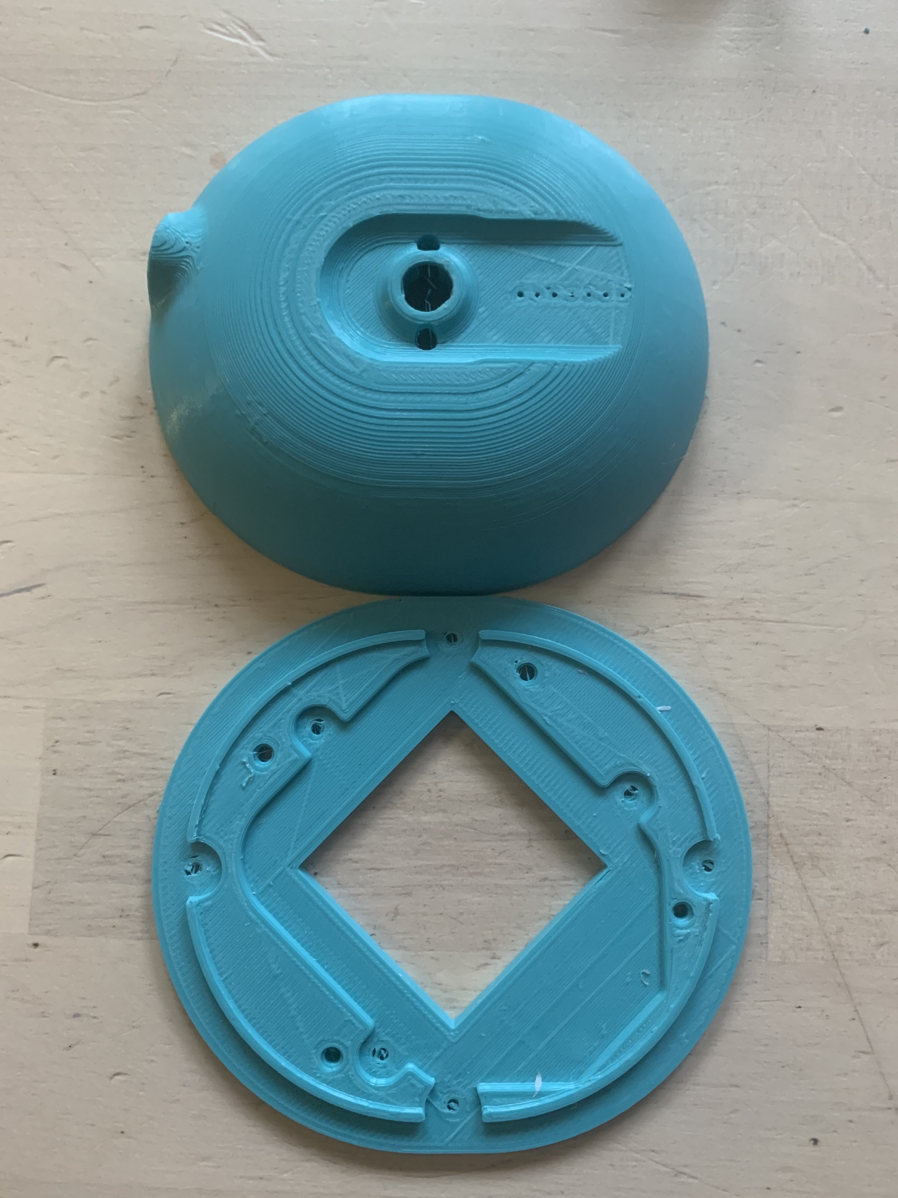
Here are the stl files for heated inserts guys:
Exactly as stock except using a 3.5mm connector, and implementing heated inserts obviously..
https://www.dropbox.com/sh/ddzghyfh2r1nj1k/AABnAwMfcxCW52jYTvR4MSwSa?dl=1
Ive included an stl for the front slider cover, as I managed to strip the thread from my original ones, so might come in useful to someone.
Inserting heated inserts into the cups for beginners: (skip this part if you know what you're doing here)
So I've used 2 different heated inserts on my build, these ones are highly recommended for inserting into the cup as they take a ridiculous amount of force to pull out:
https://www.amazon.co.uk/gp/product/B07PP2SDST/ref=ppx_yo_dt_b_asin_title_o09_s00?ie=UTF8&th=1
I used an old soldering iron (set to around 230) which did the job fine, I know there are special tools and soldering iron bits available for doing this, but I had no problem with an iron.
My method for the cup inserts is to have a perfectly flat piece of metal on a hard surface nearby, then one insert at a time, (if you're using the inserts I've linked to then they should sit nicely in the cup hole), gently place the soldering iron tip into the insert from directly above, dont push down, just use the weight of the soldering iron...when the insert is about 80% submerged quickly put the iron down and flip the cup onto the hard flat surface and push down hard, there will be enough heat to finish the insert and the result will be a perfectly straight, perfectly flush insert.
Inserting heated inserts into the baffle:
These are cheaper ones that are fine for mounting the ring to the baffle, as they are inserted from the cup side of the baffle:
https://www.amazon.co.uk/gp/product/B08H563S9W/ref=ppx_yo_dt_b_asin_title_o02_s00?ie=UTF8&psc=1
Use the same approach to inserting the baffle inserts as above, but because the surface of the baffle isn't flat, instead of flipping over onto a flat surface to finish the insert off, just have a small flat metal object to hand to finish the insert off when it is 80% submerged, again this ensures a straight, flush insert.
I had this set lying around so you dont need all of them, just the M2.5x3.5x3mm ones...remember these need to be mounted from the rear of the baffle, after you have inserted them let them cool down for a few minutes, and before doing anything slowly screw a longer 2.5mm screw all the way through from the same side you inserted them. This will push out any filament that might be blocking the insert and the hole when you mount the baffle.
The screws I have are from this set:
https://www.amazon.co.uk/gp/product/B075WY5367/ref=ppx_yo_dt_b_asin_title_o06_s00?ie=UTF8&psc=1
The screws used for mounting the ring to the baffle are M2.5x8mm
The screws used for mounting baffle to the cups are M2.5x6mm
All screws should be fitted with a M2.5x6x0.5mm washer, I can't link to the washers as I have an old selection box full of them and I have no idea where they came from.
Be careful if not using these exact screw lengths as you could screw straight through the cup.
As far as tightening goes, personally I keep screwing until I start to feel resistance, and then do a quarter turn more. Obviously it would still be possible to over tighten these, because you'll just start to crush the 3d material you used to print.
I felt it best to leave the driver mounting as normal, as without modifying the drivers themselves I couldn't see a way to improve this, so mount the driver to the baffle exactly as per the initial instructions.
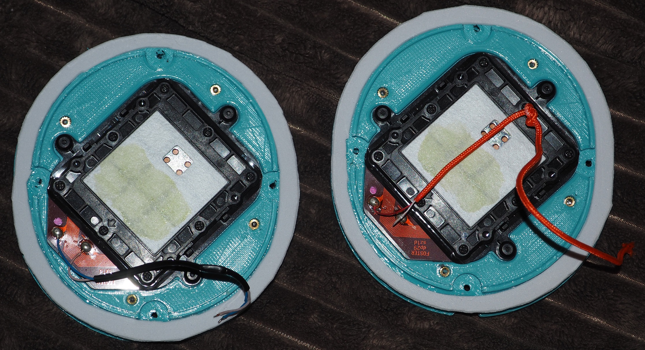
Personally I've cut reusable silicone gaskets that sit between the ring and the baffle, and between the baffle and cup, if you dont go down this route then obviously seal/glue these parts as per the initial instructions.
Any questions then just ask, any improvements or suggestions are welcome.
Good Luck !
Edit: Sorry I should point out, in your 3d printers settings, set perimeters to greater than 2, I've set mine to 4 for extra strength around the inserts.


") Thanks
Thanks 

