Official Perfboards and P2P Thread.
Aug 17, 2008 at 8:53 PM Post #31 of 49
Quote:

Originally Posted by TzeYang /img/forum/go_quote.gif
My soldering method is quite contrary to conventional soldering methods. Not sure if you guys are interested but I’ll post it anyway.


Thanks, that was really interesting. I guess it must be slower but the results are lovely. I have see some more complex "helping hands" type things which have a cushioned hand to hold components in place while soldering, which sounds good as it saves your fingers or the tape from melting.

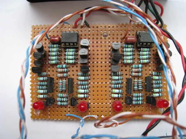
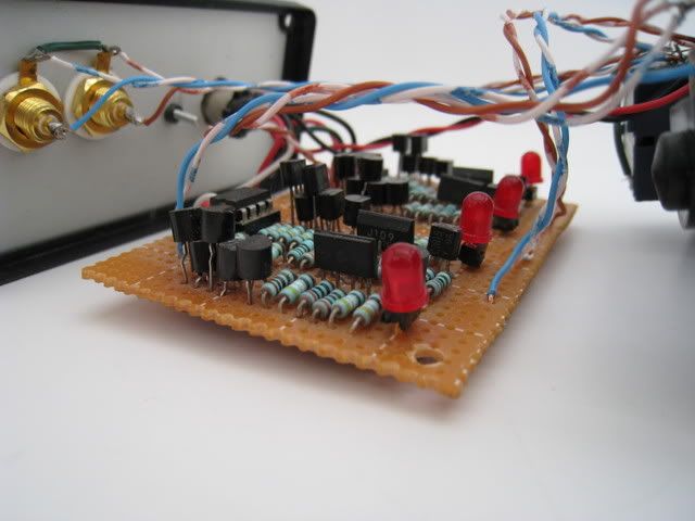
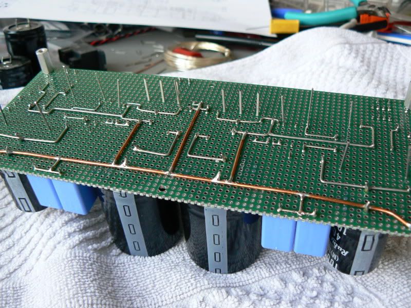
Can I ask, how do you get the long runs of solder so neat? I find it hard to do long runs like that, although it might be down to using an 18W iron. I really need to get a better one. Normally I bend long component legs over to make it easier.
 
Aug 17, 2008 at 9:30 PM Post #32 of 49
For PCB/perf work, I always solder with the full leads through the holes and bent out so they hold the component tightly to the board. I try to get as much of a physical connection as possible. After soldering, I use flushcutters to trim the leads off. Then I'll give the joint a quick reflow.

That's extra work, but you get smooth, clean joints on the pads while ensuring against cold solders.

Another side benefit is that this leaves no sharp edges from the leads. That makes it easier to wipe the board's underside with isopropyl and a rag to get rid of flux spatters.

And about the physical connections, that's one reason I love terminal strips and tie points. I crimp leads hard onto those before making a solder - a good crimp makes a physical bond and the solder just makes it even better.
 
Aug 18, 2008 at 4:36 PM Post #33 of 49
Some pics of my perf board amp. I use this technique for prototyping thru hole circuits at work, or building small fixtures. I typically use double clad Vector board, since it provide a ground plane and allows me to better secure components.

BTW, this is the PRR-Tori amp from Headwize. I happened to have pretty much everything laying around the lab and built it in a weekend a few years ago. I've since modded it it by biasing the opamp into Class A with a pair of J-FETS, visible in the pic of the bottom side of the amp.

129319009_FTVDd-L-1.jpg


129319013_Gc36R-L.jpg


129319016_wHZaC-L.jpg


The seamy underside:

129319021_JePLX-L.jpg
 
Aug 18, 2008 at 8:30 PM Post #35 of 49
Great thread guys. It's been a while since I've browsed, much less posted. A problem has developed with my Dynalo so I decided to snap some pics while it was naked. Not nearly as clean as some others or the legendary sijosae.

IMG_0090.jpg


IMG_0091.jpg
 
Aug 18, 2008 at 8:46 PM Post #36 of 49
Quote:

Originally Posted by BradJudy /img/forum/go_quote.gif
Here's some p2p that I did:

IMG_1827.JPG


j/k
biggrin.gif
It's a wire-wrap board from an old modem I had. Crazy stuff though.


I've troubleshot/repaired a lot of stuff that look exactly like that. Not fun at all. I've also done my share of wirewrap construction, including some fairly big projects. Tedious, to say the least. It really sucks when you find an error, and have to unwrap a bunch of stuff to fix what you screwed up.
frown.gif
 
Sep 30, 2009 at 4:50 PM Post #38 of 49
Edit:
Oops, Sorry, posted in the wrong window
confused_face_2.gif
 
Oct 1, 2009 at 5:17 PM Post #40 of 49
Looks great!

One quick question though, what's with the floating ~10W resistor at the bottom of the picture? If you're hoping to get anywhere near the rating of that resistor it'll need be sinked to the chassis securely and be sure to use thermal compound as well. If you haven't already read one of the data sheets for those to get an idea of just how responsible the chassis is for allowing them to be rated as high (wattage wise) as they are.
 
Oct 1, 2009 at 6:35 PM Post #42 of 49
Quote:

Originally Posted by n_maher /img/forum/go_quote.gif
Looks great!

One quick question though, what's with the floating ~10W resistor at the bottom of the picture? If you're hoping to get anywhere near the rating of that resistor it'll need be sinked to the chassis securely and be sure to use thermal compound as well. If you haven't already read one of the data sheets for those to get an idea of just how responsible the chassis is for allowing them to be rated as high (wattage wise) as they are.


Yah. I tried to enlarge the hole on the resistor as I didn't have any bolts small enough at the time. Guess what, when you do that the resistor shorts to ground and you blow fuses when you bolt it down. I had used two of them originally in the other filament supply before I added the bucking trafo, but afterwards one of the resistors for the 5965 was what was the closest to what I needed to still bring the 1626 filament down (it's on it's own trafo which was slightly overrated), so I just put it there. It's not dropping very much (less than a volt) and barely gets warm to the touch.

I need to go back and increase the 1626 cathode resistors to 1.2K or so as I'm running those tubes a little hot, but after 50-60 hours they don't seem to be any worse for wear. Planned on swapping out that big Dale resistor at the same time just to tidy things up.
 
Nov 22, 2009 at 3:42 PM Post #43 of 49
As part of a much bigger -6C33C SET amp- puzzle, here is the dual 210V power supply I have made this afternoon.
I have tried my best but I have to confess that... doing perfboarb is certainly not my strongest specialty.
redface.gif


Afbeelding715.jpg

Afbeelding718.jpg
 
Nov 22, 2009 at 5:57 PM Post #44 of 49
Quote:

Originally Posted by Ferrari /img/forum/go_quote.gif
doing perfboarb is certainly not my strongest specialty.


I'm going to go out on a limb here and tell you to be quiet. That looks fantastic!
 
Nov 22, 2009 at 6:47 PM Post #45 of 49
Quote:

Originally Posted by Emooze /img/forum/go_quote.gif
I'm going to go out on a limb here and tell you to be quiet. That looks fantastic!


I totally agree. If you're not satisfied with this, please never show us something that you're happy with
wink_face.gif
 

Users who are viewing this thread

Back
Top