New! WNA MKll Head-amp kit.
May 28, 2005 at 5:39 PM Post #421 of 764
Quote:

Originally Posted by BrokenEnglish
fine! thanks!
have you also removed r11, mike?


The incandescent lamp has been removed yup.... I replaced it with a ferrite bead inductor.

Mike.
 
May 28, 2005 at 5:41 PM Post #422 of 764
Quote:

Originally Posted by PinkFloyd
The incandescent lamp has been removed yup.... I replaced it with a ferrite bead inductor.


ah.. *cough*... sorry.. wasn't aware that...
plainface.gif
 
May 28, 2005 at 5:43 PM Post #423 of 764
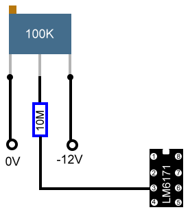
Meant to say..... solder the wiper of the trimpot (with 10M in series) to pin 3 of the LM6171.... then solder one side of the track to ground and the other side to pin 4 of the LM6171. The wiper is usually the centre leg on the trimpot.

Mike.
 
May 28, 2005 at 5:45 PM Post #424 of 764
Quote:

Originally Posted by BrokenEnglish
ah.. *cough*... sorry.. wasn't aware that...
plainface.gif


A zero ohm link will do but I had a couple of spare ferrite bead inductors so used them instead.

Mike.
 
May 28, 2005 at 5:52 PM Post #426 of 764
Quote:

Originally Posted by BrokenEnglish
ah.. *cough*... sorry.. wasn't aware that...
plainface.gif


Yep, the bass will go down a couple of octaves deeper when you replace the 22R incandescent output lamp with a zero ohm link.

Mike.
 
May 28, 2005 at 8:04 PM Post #427 of 764
Quote:

Originally Posted by PinkFloyd
On the subject of the TLE2462 being used in the rail splitter I asked Dr. White and here's his take on it:

This is very easy to arrange, you simply remove the two 10k resistors in the rail splitter (and possibly the associated 100nF cap too) and replace them with the TLE2426. The TLE2426 In terminal goes to the rail splitter positive line ( +V ), the Common terminal to the rail splitter negative line ( -V ), and the Out terminal goes to what was the junction of the two 10k resistors. The LM6171/BD139/BD140 then acts as a high current buffer to the TLE2426


what do you think are the advantages of switching an additional tle2426-railsplitter in front of the railsplitter-part of the mkII, mike?
 
May 28, 2005 at 8:16 PM Post #428 of 764
Quote:

Originally Posted by BrokenEnglish
what do you think are the advantages of switching an additional tle2426-railsplitter in front of the railsplitter-part of the mkII, mike?


I doubt it will sound any better but it will measure better on paper I'd imagine... the TLE will conform to better tolerances than the 2 10K resistors... hell It's worth a go, particularly considering I've got a few of them sitting about doing nothing. Plus it will save on board space should a MKlll ever be on the cards and negate the need for resistors, capacitor etc.

Dr. White is going to try one over the weekend to see how it measures up so I won't fit one until I get the all clear from WNA along with the measurements.

Mike.
 
May 29, 2005 at 3:57 PM Post #429 of 764
Hi

Mike, I'm glad to hear your dental health is good again… some of your recent posts seemed horror tales. I wish you new fun moments playing with op-amps, caps, resistors, trimmers and a soldering iron and enjoying music…
wink.gif


Regarding the debate on the capacitors in WNA amp, I’d like to post my opinion. I must admit that my electronic knowledge is very basic, and this post is based mostly in ideas picked from this and other forums, my listening impressions and (I think) a little common sense.

The sound of the LM6171 op-amp is truly special and I’d like to keep it. The WNA hp amp is optimised around it and there is an unanimity about its fast and transparent sound, if properly implemented, that I’ve not found about other op-amps (not even the OP627 or AD843). However, according to several posts in this forum, it has a weird behaviour in dc offset (Mike has even measured it). With other op-amps there is no need to prevent it perhaps because they seem inherently “dc offset-proof” (which the LM6171 is not). Therefore, it is possible that the LM6171 generates itself a dc offset at its output, that amplified by the following stages in the amplifier can be dangerous to the headphones connected to the amp, even damaging them.
The resistor-and-trimpot solution is good but it is complicated to implement (it needs careful and individual measuring and adjustment) and perhaps changes in temperature or any abnormal situation can drift the dc value for what it is adjusted, making it nearly useless.
An output capacitor in series is the bullet-proof solution and a good sounding one, assuming the cap is high quality (to avoid a loss of transparency or a mushy sound) and high value (to avoid phase shifts and an impaired bass response). I hope the Black Gate bipolar Nx 1000uF/25V I use is up to this task. In any case, a small loss of quality (if it does exist) would be compensated by the peace of mind of knowing that under no circumstances my beloved (and expensive) Grado HP-2 headphones can be destroyed by dc amplified by the WNA amp, simply because this would have been blocked by the output caps before reaching the outside world.

However, I’m going to keep the input caps out. Without them, the amp sounds better than ever and I assume it is safe not to use them, as the majority of sources have no problems of excessive dc offset and many have their own output caps, making the input caps in the WNA redundant (I’ve measured various CD and DVD players, with readings from 0 to 1-3 mV). And, even if all goes wrong and, for whatever reason, a burst of dc coming from the source goes into the "input cap-less" WNA amp and damages any of their components, their repair would be a lot easier and cheaper than doing so with a pair of expensive headphones or (if I use the WNA as a preamp in a future) a power amplifier and a pair of loudspeakers, because these all were protected by the output caps in the WNA amp. Remember that the modest cost of Dr. White’s little amp is far below its great musical performance.

BTW, I have a question to Udo and Mike, regarding the crackling noise when I turn the volume all the way down. Using an insulating glove or touching one of the rear screws of the pot with a wire connected to ground has no effect. Is it dangerous to my headphones or whatever is connected to the output of WNA amp or simply is it a small nuisance?. I assume that with output caps it is impossible for dc offset to find its way outside the WNA amp. I’ve read in the HeadRoom webpage that in their AirHead hp amp (which I have, as my portable, battery-powered amp) they use output caps, but not caps around the volume control, in order to get the best sound quality, although the price to pay is a small noise when turning up or down the volume, similar to that I have in my “input cap-less” WNA amp. If this crackling is not dangerous, perhaps I don’t even bother to fix it
icon10.gif
.

Regards
Jose

PS.: Udo, the PSU you have built is impressive and I’m looking forward to hear your listening impressions, as I’m sure that the power supply is a very important factor if one searches truly the ultimate sound quality. I have a WNA cascode PSU connected to my WNA hp amp with great sonic results, but I’m a little confused about the different wiring options and I need a bit of help and advice… but I’ll left that for another post…
 
May 29, 2005 at 4:48 PM Post #430 of 764
hi jose,

first of all, i perfectly understand everyone who enjoys the acoustical benefits of leaving those input-caps out. unfortunately in this case there seems to be no way to prevent the lm6171 from straying some - then increasing - dc-offset back to the inputs while you turn the volco - and that causes the crackling we are hearing. in fact you could read some minor spikes of mV DC with your DMM while you readjust the volume: given the input-capless mkI i read values between 2-10mV for a few tenth of seconds - nothing to worry about, but obviously audible as crackling noise. your black gates maybe do a better job in filtering the offset out at all. just test it.

of course i also understand your feeling of protection behind your output caps. personally i thought about implementing amb's epsilon 12 circuit for the same reason, because it can detect dc-offset and mute the outputs. but i'm not sure, if i'm skilled enough right now, to build it...
rolleyes.gif


hm.. and my psu... well... let's say, it is a built in progress. i'd bet you could yield better results with dr. white's cascode psu, configured as dual-voltage psu (should be no problem at all - all you'd need are some jumpers, different cables and some some sort of three-pole-connectors psu->wna ha). to keep it short: i heard nearly no audible advantages after switching from my single-voltage-supply with the wna-railsplitter behind to my my simple dual-lm317 psu. the only thing that matters there, is that i'm now able to play with higher rail-capacitance. it's quite time-consuming to test different values of faster (tantalum, foils, ceramic) and slower (electrolytic) caps inside my amp but it is also very interesting: it's like fine-tuning or "voicing" the amp. if you'd like to join that game, you'd have to take the dual-voltage route, because the wna-railsplitter - as mike and i had to realize - is not able to handle capacitances higher than 220µf.
but to be honest, for now i'm not too happy with my results. i have more bass, but i'm missing some presence and resolution in the upper parts of the audio spectrum. maybe that's due to progreding burn-in effects in lots of caps. and there are other parts on my optimisation-list: today for example i tested the effects of cables with higher diameter (connection transformer->regulator) and found, that most likely i didn't use the right (i.e. to small) panel-wires in my psu. that means, i have to rewire the whole panel-stuff...
rolleyes.gif
eek.gif

well... it never ends...
lambda.gif


cheers,
udo

/edit: one additional important note on single- vs. dual-voltage psu's for the wna ha. there's one BIG, potentially dangerous disadvantage of dual-voltage psus: i expect a real BLAST of dc-offset in case one of the rails of my psu collapses (due to simple cable break for example). those things should never happen with the railsplitter, that adjusts the ground in symmetry between the + and - rails.
 
May 29, 2005 at 5:33 PM Post #431 of 764
Hi Jose,

I'm afraid input caps are essential with the LM6171. you can safely dispense with the output caps and fit the 10M and trimpot and the DC will not drift at all..... I set mine to 0.00mV on both channels about 26 hours ago and the reading is still 0.00mV on each channel.

If you think your amp sounds good without input caps you'll be amazed at how fantastic it sounds with input caps but without output caps... It really is the electrolytic output caps that are getting in the way of truly glorious sound..... since removing them and fitting the 10M and trimpot It's like listening to an entirely different amp.. just pure crystal clear sparkling sound..... superb.

Honestly, once you fit the trimpot / 10M and adjust to 0.00mV per channel it doesn't drift at all. Just make sure you solder the 10M resistor onto the wiper of the trimpot very well and shrinkwrap it to ensure a good, robust, mechanical connection.

If you're not happy with this you could go down the long route which would involve soldering two leads onto pin 3 and 4 of the LM6171 and terminate these leads with crocodile clips....... next arm yourself with a couple of hundred +/- 5% carbon film resistors and work your way through the resistors until you find one that matches as close to 0.00mV as possible (anything under 10mV is ok) when you find one that is pretty close to 0.00mV then you just solder it between pins 3&4 of the LM6171 and you're good to go.

The trimpot is a better way of doing it (and faster) but there should be no reason any massive DC will reach your headphones unless something like the resistor drops off (very unlikely) even if the full DC of a naked LM6171 got through It's unlikely it would blow your headphones... so, as I say, don't be frightened to remove the caps and replace with 10M and trimpot... many amps use trimpots to adjust the offset and resistors are pretty unlikely to fail in this application (touchwood!)

All the best.

Mike.
 
May 29, 2005 at 8:39 PM Post #432 of 764
I haven't tried the TLE 2462 yet but drew a couple of diagrams up in photoimpact and sent them to Dr. White just to be sure I was connecting the TLE 2462 to the right places........ I'm no graphics expert so please excuse the strange diagrams...... one shows the Underside PCB connection and the other shows the top connection...... in both instances R12 and R13 are removed (10K resistors)

attachment.php

Underboard connections

attachment.php

Top of the board pad connections


Dr. White tried the TLE 2462 today and says:

"Mike,
Both of your diagrams are correct. I tried it this morning and it works fine. I'm not sure if there's any benefit though. Using two 0.1% resistors to define the midpoint of the supply will give better accuracy than a TLE2426 which is good for around 1%. One of the 10K resistors is bypassed by a 100nF capacitor which will give you some noise reduction - the TO92 version of the TLE2426 doesn't have a noise reduction pin so you lose out there too. Incidentally the 100nF capacitor should either be left out or increased to more than 1uF for guaranteed stability ( see ti datasheet ). The one advantage that the TLE2426 has is that its cheaper than two 0.1% resistors. I didn't do any critical listening so I don't know whether the TLE2426 has any effect on the sonics.

Regards, David."


Armed with that info I will not be removing the 10K resistors from R12 & R13 and fitting a TLE 2462...... however, if I were building another WNA then I would fit the TLE 2462 in place of the 0.1% resistors as it would be more cost effective and basically do the same thing....... to hell with it, I'll fit a TLE 2462 in situ tomorrow and do some "critical" listening
evil_smiley.gif
In for a penny in for a pound..... It's an easy affordable tweak so may as well give it a go.

Mike.
 
May 29, 2005 at 8:54 PM Post #433 of 764
On the subject of DC offset that Jose posed Dr. White responds:

"Fortunately such events rarely occur in normal use; I've never had a "normal use" dc offset fault with any amp, power or headphone, in goodness knows how many years of designing/buliding/tweaking. BUT, once in a very blue moon such things do happen, and the WNA will happily toast any attached headphones. It can deliver an amp or two for a short period of time - long enough to fry headphones. In normal use I would estimate that you'd be very unlucky to have such a failure in 30-40 years of hard use. If you want belt and braces protection you can use a headphone protection unit that disconnects the headphones in the event of a dc offset. As I mentioned to you a couple of times previously I'm in the process of upgrading my loudspeaker protection unit to cater for headphones ( this preceded ambs unit ). The pcb design is now complete and kits should be available in 3-4 weeks time. The trip level can be set to whatever you like ( typically 50mV ) and it provides led indication of fault and normal conditions. It uses a chunky 8A relay with big silver stud contacts to do the business. Power required is around 50mA at +12V and 5mA at -12V. The power can be either ac or dc - a little 3VA transformer will do fine. You can put the unit in the same box as the headamp, if you have room, or in a separate box."

You've got to keep this guy on his toes
wink.gif


Nice one.
 
May 29, 2005 at 9:47 PM Post #434 of 764
Quote:

Originally Posted by PinkFloyd
On the subject of DC offset that Jose posed Dr. White responds:

[...]Power required is around 50mA at +12V and 5mA at -12V. The power can be either ac or dc - a little 3VA transformer will do fine. You can put the unit in the same box as the headamp, if you have room, or in a separate box.


so... why not use the amp's psu, in case anybody out there uses a dual-voltage psu?
lambda.gif


/edit... of course another voltage splitter should also be able to do the job... hm... have to ask dr. white first.
 
May 29, 2005 at 10:04 PM Post #435 of 764
good question awaiting answer. In the meantime I'm prepared to take the risk re: the 10M/ trimpot scenario......... sounding awesome and unlikely to fail "ever" let alone in "30-40" years.

Class on a stick!
 

Users who are viewing this thread

Back
Top