


adn6244
Head-Fier
- Joined
- Sep 9, 2008
- Posts
- 57
- Likes
- 5
What i read from the setup page :
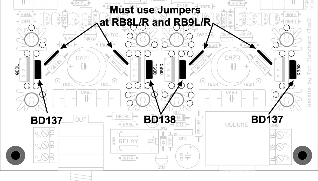
"Both DB channels should average below 50mV or thereabouts, but this depends on the JFET variance. I've seen some with minimum voltage of 25mV and some with a minimum voltage of over 40mV. If the bias voltage is much higher than 50mV, turn the amp off until you figure out whether the trimmers are operating correctly. Once you confirm that the bias voltage is safe, then leave the amp on and proceed with setting up the power supply voltage and tube bias settings, first."
I started to ensure DB bias is below 50mV and proceed to adj the PS bias. I got the 27V for PS and now stuck with Tube bias.
I am sure I got the DB bias ref point correct. I have a feeling I may have snap the Bourns as I went past the click warning twice. I'll double check again later.
Thanks for your prompt reply, really appreciate it. Will update you later if I am able to resolve it...thanks again.


