New Millett Hybrid Maxed Amp
Apr 13, 2009 at 11:45 PM Post #5,686 of 6,727
Quote:

Originally Posted by smegger /img/forum/go_quote.gif
was thinking that about the parallel, school physics coming back to me!

i think ill give the wire up a go tomorrow. and give the thing a listen.

Would i need to fuse the board or will the fuse in the power supply be enough?

any idea what fuse i would need?

cheers tomb


A 1A slo-blo would probably do the trick. With a raw transformer, it's a good idea to use the fuse on the board. The fuse on the line side will protect the primary, but there's nothing to protect the secondaries unless you use the fuse on the board.
 
Apr 14, 2009 at 2:05 AM Post #5,687 of 6,727
Are your taxes done yet Tom?
wink.gif


Just finished mine today...
 
Apr 14, 2009 at 4:27 PM Post #5,688 of 6,727
Problems
frown.gif
frown.gif
frown.gif
frown.gif


think i left my amp on too long the first run!!! didnt see the bit about turning down Rb12 L/R

now been checking the values getting 28/9mV on the left chanel

getting like 600+mV on the right one! this is way to high!

What is likely to have broken? trimmer or have i fried the right channel?

can i check this?

no burning smell or anything one had the amp on like for a minute tops the first time.
 
Apr 14, 2009 at 5:03 PM Post #5,689 of 6,727
Quote:

Originally Posted by smegger /img/forum/go_quote.gif
Problems
frown.gif
frown.gif
frown.gif
frown.gif


think i left my amp on too long the first run!!! didnt see the bit about turning down Rb12 L/R

now been checking the values getting 28/9mV on the left chanel


I hope you mean 28mV, which essentially means the RB12L trimmer is turned all the way down right now. Leave it for now so that you can use this channel as your reference for "what's right."

Quote:

getting like 600+mV on the right one! this is way to high!


Yep - that's too high. However, are you saying it's this high with the trimmer turned all the way down or is this what you measured without adjustment?

Quote:

What is likely to have broken? trimmer or have i fried the right channel?


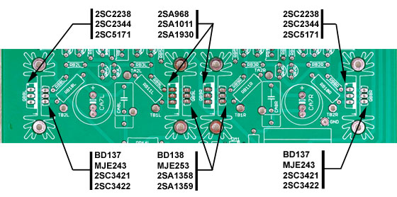
It takes quite a few minutes to really smoke one. Most likely, you've got a part out of place. Go over VERY carefully the parts you have in the right channel buffer compared to the left's. Make certain you have the same resistors in the same positions and the same TO-92 transistors (e.g., 2n5088's in the right place vs. 2n5087's in the right place). Check to make certain that you didn't swap the output transistors from the positions on the left channel. Refer to this diagram on the MAX website for proper location of the output transistors:
BJTpositions.jpg


Also refer to the buffer biasing setup page on the MAX website:
MAX Setup and Bias Settings

What about the tubes, voltage adjust, volume control position, etc? Were these measurements made with the tubes in - were they biased? What was the voltage? Was the volume knob turned down to zero? You must have the volume down when you bias. You should kick the power on and off to make these measurements until you solve the buffer bias problem. Still, one of these things may be your problem.

By the way, is there any chance you used MOSFETs? I noticed in your pics that you went with the taller heat sinks. The layout pic above and setup reference will not apply with MOSFETs - we'll have to look at the MOSFET-MAX website, instead.

Quote:

can i check this?

no burning smell or anything one had the amp on like for a minute tops the first time.


Yes, you can check this. It may take some effort, but we usually solve these things.
wink.gif
smily_headphones1.gif
 
Apr 14, 2009 at 5:22 PM Post #5,690 of 6,727
had a quick check, def not mosfets,

tubes in volume down when i did the test,

both trimmers turned down fully down as per the website got 28mV in the left and like 600mV in the right

i checked the resistance of the trimmer pots by using my multimeter and the outer two pins on the pots and tried to check adjustment by taking different reading while turning the screws and the left one gives different valuse as expected however the right one doesn't seem to change?

could this be the problem???

il have a more detailed check over the components now.


EDIT

Just set the Power Supply to 27v

getting 28.7mV on the left channel


getting 700+mV on right channel

Tube bias wasnt set for this

EDIT 2

just noticed QB1R is in the wrong way round correcting now

EDIT 3

WOOO Getting the right numbers now to drive to my student flat to get my K601s!

thanks TOMB!
 
Apr 14, 2009 at 6:58 PM Post #5,691 of 6,727
Quote:

Originally Posted by smegger /img/forum/go_quote.gif
<snip>

EDIT 2

just noticed QB1R is in the wrong way round correcting now

EDIT 3

WOOO Getting the right numbers now to drive to my student flat to get my K601s!

thanks TOMB!


Way to go!! You did it, though!

How's the xfmr? Any hum with it to the side like that? If not, order those panels, now!!
smily_headphones1.gif
 
Apr 14, 2009 at 9:23 PM Post #5,692 of 6,727
Cant hear any thing out of the ordinary in normal listening, any way to isolate it just to be sure?

Also my k601s now sounds awesome! who ever said these had no bass!

Really enjoying the first sounds out of my amp!
 
Apr 14, 2009 at 10:17 PM Post #5,693 of 6,727
Quote:

Originally Posted by smegger /img/forum/go_quote.gif
Cant hear any thing out of the ordinary in normal listening, any way to isolate it just to be sure?

Also my k601s now sounds awesome! who ever said these had no bass!

Really enjoying the first sounds out of my amp!


Well, the K601's are pretty revealing. So if you don't hear anything, chances are things are fine. I'm no expert in such things, but what seems to be certain is that you need to use steel in order to block any potential hum. Some have encased the entire toroid in a steel box. Others have put a steel divider in the case between the toroid and AC and the rest of the amp. Keep in mind, though, that many people use toroids bare (they are naturally less noisy) - just as you had it in your mock-up layout - and never have an issue.

I only mentioned it to urge a bit of caution before you spent all the $$ on the panels. As I said, if you don't hear it - I'm sure everything is fine.
smily_headphones1.gif
 
May 2, 2009 at 10:58 PM Post #5,694 of 6,727
Finally I'm done university for the year, and I can start again on finishing up my MAX build. I've been mulling over ideas in my head for an enclosure, and I had a post saved from the forums of a nice case, but I can't remember what brand the case is... is anybody familiar with this? It's Ferrari's build.

P1010059.jpg


More photos at the link here.

Thanks!
 
May 2, 2009 at 11:16 PM Post #5,695 of 6,727
Quote:

Originally Posted by Takaji /img/forum/go_quote.gif
Finally I'm done university for the year, and I can start again on finishing up my MAX build. I've been mulling over ideas in my head for an enclosure, and I had a post saved from the forums of a nice case, but I can't remember what brand the case is... is anybody familiar with this? It's Ferrari's build.


Looks like one of these DACT enclosures:

DACT Enclosure - Soundlabs Group
 
May 3, 2009 at 1:22 AM Post #5,697 of 6,727
IMO ATI Research had the nicest enclosures available. It's a real shame they're out of business. The other cases seem too rectilinear...

Thanks for the help in identifying it, though. I'm still not sure what I'm gonna choose for an enclosure, but I'm looking at modushop.biz more closely now.
 
May 3, 2009 at 9:39 PM Post #5,699 of 6,727
TomB and Colin,

Did you guys try adding a Polyfuse in series with DR3 in the V1 MAX board? I know the ground configuration was a big contributor in lowering the noise floor of the MiniMAX (and upcomming V2 MAX), but I was just wondering if adding PF1 to my V1 MAX would be a measureable improvement.
 
May 3, 2009 at 10:02 PM Post #5,700 of 6,727
Quote:

Originally Posted by WilCox /img/forum/go_quote.gif
TomB and Colin,

Did you guys try adding a Polyfuse in series with DR3 in the V1 MAX board? I know the ground configuration was a big contributor in lowering the noise floor of the MiniMAX (and upcomming V2 MAX), but I was just wondering if adding PF1 to my V1 MAX would be a measureable improvement.


Nevermind! I just looked at the board layout of the V1 MAX and realized that there would be a lot of traces and ground planes that would need to be cut to make this work.
frown.gif
 

Users who are viewing this thread

Back
Top