Quote:
Originally Posted by John Wilson /img/forum/go_quote.gif
Sad news...I can't get the DB's on one side below .940 mv and the other side below .835 mv!!! The tubes bias fine at 13.5 v, And ps at 27v. For what it's worth the MJE 243 and 253's are about 9 years old...never used..stored in there bags. May I;ll get new ones. JW
|
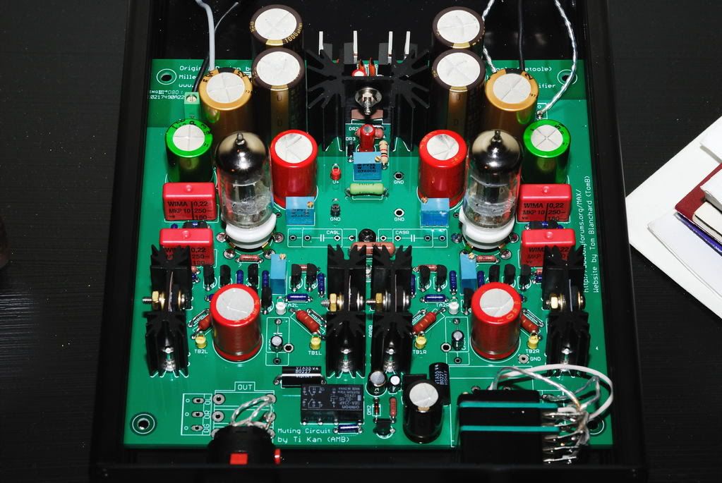
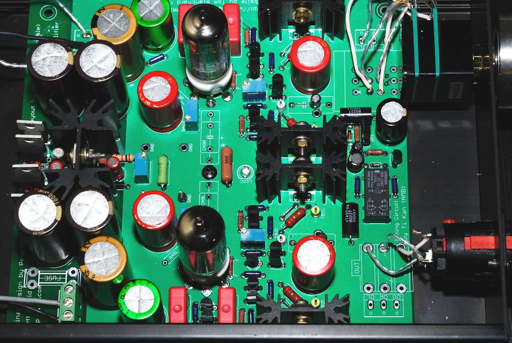
I've looked at your pic on page 366 of this thread. You've got a real good pic there of the DB section. A visual inspection doesn't indicate anything wrong. So, let's start the standard drill, John:
1. Verify the test points that you are trying to measure. The test points do nothing but measure the voltage at the leads of the RB10 or RB11 resistors.
Left Channel: One probe is in TA2L. The other probe is in TB1L or TB2L.
Right Channel: One probe is in TA2R. The other probe is in TB1R or TB2R.
2. If that's correct, you need to verify your parts.
Trimmers:
RB12L and RB12R are 2K trimmers
Transistors:
Even to Odd on the small transistors to the pads on the board. 2N5088's go on QB3, QB5, and QB7. 2N5087's go on QB2, QB4, and QB6.
QB1 is the PN4392 JFET.
MJE253's go on the middle sinks on the Right side of the sinks.
MJE243's go on the outboard sinks on the Right side of the sinks.
Resistors:
RB1R: 1K ohm
RB2R, RB3R: 10 ohm
RB4R, RB5R: 100 ohm
RB6R, RB7R: 220 ohm
RB8R, RB9R: JUMPERED
RB10R, RB11R: 2.2 ohm Power Resistor
Please, DON'T CHEAT - make an honest attempt at this and let us know. If this doesn't indicate something, there are other things that we can try.