Awesome, thanks guys. I searched, but I guess I didn't go far enough through the posts to find that. Last question, what do you recommend biasing the Mosfets to? I saw the range on the website of 176-264mV, and 220-275mV elsewhere. I've got it biased at 180mV to start, but what would be optimal, or is there a page explaining it similar to the one for tube bias?
Thanks!
Sorry for all of the bone-headed questions. I've got it now. It's been a long week. Tomb, your patience is incredible and appreciated. Sorry again guys.
Thanks!
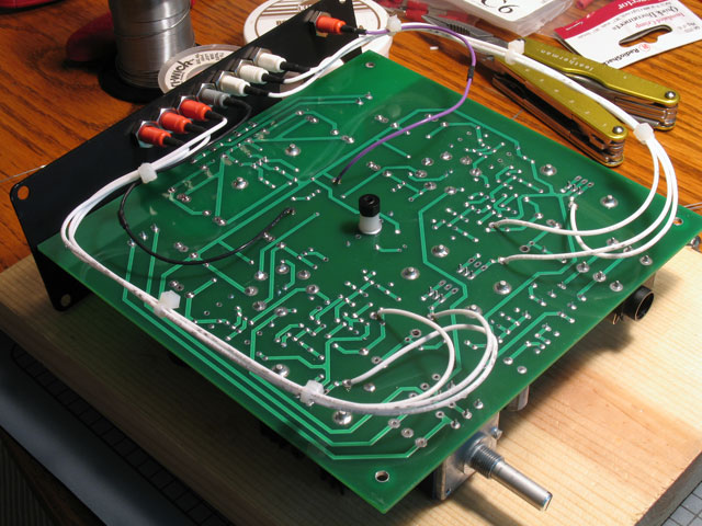
I just biased my Mosfets. It's weird. In order to obtain 100mA, I need to get them to 282mV. It seems weird that they wouldn't be exactly the same as the values on the website. Any thoughts on what I did wrong?
I just biased my Mosfets. It's weird. In order to obtain 100mA, I need to get them to 282mV. It seems weird that they wouldn't be exactly the same as the values on the website. Any thoughts on what I did wrong?
You can't read milliamps with your meter - not unless you broke the circuit to the MOSFETs somewhere and wired the meter in series with the MOSFETs. It can't be done without screwing up the PCB.
The whole point about biasing the buffer is that we're trying to achieve a certain value in current: about 125 milliamps. The way we do that is to measure mV across one of the power resistors that are connecting the MOSFET pairs, which your meter can do quite easily without having to be placed into the circuit. RB10 or RB11 is 2.2 ohms. So, if you divide the measurement of millivolts by 2.2, you get the value of current in the circuit in milliamps. Thus, to have 100ma bias in the buffer, you should adjust RB12 (the buffer trimmer in each channel) until you read 220mV (2.2 x 100ma, I = V/R). So, right now you have 282mV/2.2 = 128ma. (That's pretty close to 125ma - I'd leave it there.
)
By the way:
for TB1R or TB2R with TA2R: TB1R with TA2R measures across RB11R, TB2R with TA2R measures across RB10R - take your pick for the Right channel.
for TB1L or TB1R with TA2L: TB1L with TA2L measures across RB11L, TB1L with TA2L measures across RB10L - take your pick for the Left channel.
If you try placing your probes across the leads of one of the resistors above, you'll be reading the same thing as those test points.
Looks like I had the English screwed up on the webpage's table for this stuff, so I've corrected that.
P.S. Anytime someone mentions measuring the current on a built PCB, they are more often than not talking about measuring the voltage across a resistor of known value. The measurement in voltage divided by the resistor's ohm value is the current through that resistor. Wiring a meter in series within the circuit is always the last choice for measuring current, because you can very easily blow up a meter if the current range setting is exceeded.
TomB, let me reiterate my last posting - your patience and help is spectacular. Thanks so much. A Millett Mosfet lives and sounds INCREDIBLE! I couldn't have done it without your help! Thanks!
This site uses cookies to help personalise content, tailor your experience and to keep you logged in if you register.
By continuing to use this site, you are consenting to our use of cookies.