New Millett Hybrid Maxed Amp
Feb 7, 2012 at 4:03 AM Post #6,331 of 6,727
One more stupid question. On the Max 1.2 board, I've noticed that the silk screening for the trimpots have a little bit of a shape to one side. I assumed that went to the back of the trimpot. I understand that it won't matter as the trimpots are linear, but it will effect the way I turn the trimpots for adjustments. Is the side with the two "bumps" the back of the trimpot or the front?
Thanks, yet again!
 
 
Feb 8, 2012 at 6:32 PM Post #6,332 of 6,727


Quote:
Quick question. I'm just finishing up my Mosfet Max, and am starting on the casework. The diagrams are a little confusing to me. Should I be drilling out the top and bottom of the case or just the top? It would make sense that it be both so that air flows through the case, but hey, what do I know? Anyway, any help would be appreciated!
Thanks!


You should drill both.  Make certain that you have rubber feet that allow the air to circulate from underneath.  It would be a waste to drill holes in the bottom and then lay it flat on a surface, covering the holes up.  There's a boundary layer in effect, too, so get rubber feet as tall as you can.
 
If you're enterprising, there's no need to duplicate the drill pattern that's used on the top.  You can simply drill some 1/4" holes somewhat spread out on the bottom.  You should have more "free area" on the bottom than on the top, though, so get out your calculator and add up the circular area of the holes.  The top is based on 3/16" diameter holes, so - each 3/16" hole is 0.0276 sq.in.


Feb 8, 2012 at 6:35 PM Post #6,333 of 6,727


Quote:
One more stupid question. On the Max 1.2 board, I've noticed that the silk screening for the trimpots have a little bit of a shape to one side. I assumed that went to the back of the trimpot. I understand that it won't matter as the trimpots are linear, but it will effect the way I turn the trimpots for adjustments. Is the side with the two "bumps" the back of the trimpot or the front?
Thanks, yet again!


Yes, meaning the back of the trimmer is the side with the glue - not the writing.
 
 
Feb 9, 2012 at 1:30 AM Post #6,335 of 6,727
I'm glad I just re-read a few pages of this forum. I installed my QB2/3 backwards. Oh well, I had more I wanted to do anyway.
 
So. Now, for my stupid question of the day: What are the pads labelled IS 1/2 for? They are in back by the input relays. I looked through a bunch of pictures and can't seem to find anyone using them.
 
Also, why would you want to bypass the fuse on the power input? That's just out of curiosity.
 
Thanks again!
 
Feb 9, 2012 at 8:19 PM Post #6,336 of 6,727


Quote:
So. Now, for my stupid question of the day: What are the pads labelled IS 1/2 for? They are in back by the input relays. I looked through a bunch of pictures and can't seem to find anyone using them.
 
Also, why would you want to bypass the fuse on the power input? That's just out of curiosity.


IS 1/2 is where you can wire a switch for switching between the two separate inputs. A simple SPST switch can be used to switch between two input sources. As an example, here is how I switch between the RCA input jacks and an internally mounted GrubDAC:


As for the fuse question, I would highly recommend using one, however, the board supports the option of not using one. Saves you a bit of money and complexity I suppose. IMHO, penny-wise, pound-foolish not to use one. Always highly recommended.


Feb 9, 2012 at 10:52 PM Post #6,338 of 6,727


Quote:
Wait, I thought the relay circuit made the switch unnecessary.
 
I am using the fuse, I was just curious why one would not want to.


A switch can potentially add noise through cross-talk in the contacts.  The relays do this as well, but it's controlled much better and with the right circuit, is well below the S/N ratio of the amp.  As far as the MAX V1.2 PCB is concerned, the switch is required.  You will never be able to switch to the RCA inputs if you don't use the switch and the relay scheme - unless, of course, you bypass the entire arrangement.
 
As for the fuse - to be honest, I was against it in the beginning and that's why I suggested to cetoole that he keep the option of feeding power through either way.  I'm not aware of another amp that uses a fuse on the PCB when it's fed with a walwart power supply.  Fuses are absolutely needed if the amp is fed directly from wall power, but that's not the case with the MAX.  So it seemed to cause more problems than it helped in the early going.  I was a complete convert, though, because over the years, it's proven to be a good thing.  I thought it only protected the walwart, but experience has shown it protects the entire amp when builders have screwed the diamond buffer. 


Feb 10, 2012 at 12:54 AM Post #6,339 of 6,727
Tom,
With the newest board, the switch is necessary? I didn't realize that. I assume any SPST switch will work. Which set of contacts are used when the switch is opened/closed? Sorry for being such a drain, I'm just a little confused.
 
Thanks as always for all of your help.
 
Feb 10, 2012 at 11:13 AM Post #6,340 of 6,727


Quote:
Tom,
With the newest board, the switch is necessary? I didn't realize that. I assume any SPST switch will work. Which set of contacts are used when the switch is opened/closed? Sorry for being such a drain, I'm just a little confused.
 
Thanks as always for all of your help.


If you populate the input relay-switching, the default (relays de-energized) is only one of the signal input punchdown blocks.  You can never change the input to the other punchdown block unless you throw the switch.  Something is needed to energize the relays to switch to the other input - that "something" is Switch S1.  There are only two terminals, so it can be any old SPST switch - as long as it isn't momentary - that would be quite irritating.
 
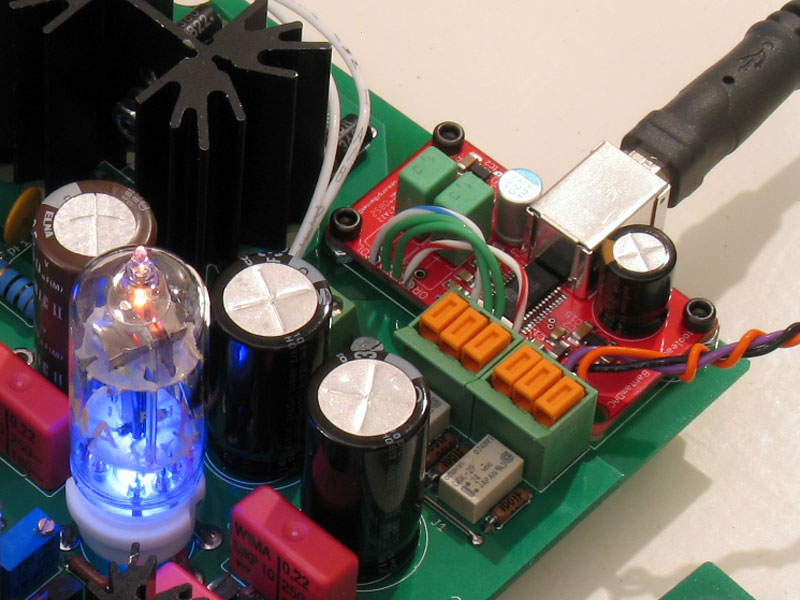
I believe the left input punchdown block is the one that is in the circuit with the relays de-energized, but you can't really tell once it's wired in and if you've used a toggle like I did (no way to physically tell ON or OFF), so don't take that as gospel.  Maybe jdkJake knows which is which.  Here's my 2nd prototype (production PCB's are RED):


EDIT: the two white wires curving around behind the heat sink are the wires to the two-position terminal block for Switch S1.  I used long wires on mine so I could mount the switch on the front plate.  It's easy to tell the output wires from the BantamDAC going to the left-hand input punchdown block.  The orange, purple and black wires come from a "test" pair of RCA jacks.  So, two input sources - one the onboard BantamDAC (could now be a GrubDAC or SkeletonDAC, too) and the other to a standard pair of RCA jacks, whichh could be connected to anything.
 
The two mini-relays are energized in an either-or fashion by throwing the switch.  However, one of the relays is energized by default when the power is on to the amp.  The resistors are there to sink an un-used relay's output to ground, which cuts down on the cross-talk between the contacts.  Both are fed from a TO-92 linear regulator at 24VDC.  The jumper is there because cetoole (the designer) didn't want to break the groundplane above the signal traces.  There is also a suppressor diode that works better than the old 1N4148 to cut down on the potential arcing between relay contacts and will promote long-life in the relays.
 
The relay circuit changes were also incorporated into the output relay-delay circuit for headphone protection.  The old Zener-diode and high-power transistor arrangement with its legacy in the e22 design is gone.  Instead, a single TO-92 linear regulator is used and the headphone relay is 24V.  This change significantly cut down on the transient voltage that many people see at cut-off.  (The time delay prevents headphones from seeing any transients on power on, but power off has always been a bit of an issue with headphone delay-relays.)
 

Users who are viewing this thread

Back
Top