New Millett Hybrid Maxed Amp
Apr 27, 2008 at 10:11 PM Post #4,622 of 6,727
Quote:

Originally Posted by Phil Townsend /img/forum/go_quote.gif
When I go to set the various bias voltages should there be a load on the output?
ie: Do I plug in a set of headphones...cheap ones just in case?
Phil


No. You don't need a headphone load to adjust any of the bias voltages.

Since you mentioned a pair of cheap headphones, though - it's always a good idea to have a pair to plug in for the very first time on a newly built amp. Better yet, just quickly check for offset at the heaphone jack before plugging something in. Wait until the relay closes, though, or you'll get zero voltage and zero sound. Offset should be on the order of 1mV or less.
smily_headphones1.gif
 
Apr 28, 2008 at 2:04 PM Post #4,623 of 6,727
I have a question for everyone.

I have (3) MAX boards and (5) BJT combos for the DBs. I'm installing these in a NABU enclosures so I have plenty of room. I want to use quick connectors so I can build up the three boards with different DBs and swap them in to my console easily for comparison testing. I know Phoenix Contact makes the connectors I need for the terminal blocks, but what can I use for the volume pot wires and RCA jacks? My volume pot will not be board mounted for any of my builds. I am willing to give up a little SQ for convenience, but once I pick the combo I like for each console, I will remove the quick connector and solder all connections to the boards.

This setup will allow me to compare a few different cap/BJT or MOSFET combos that haven't seen built or discussed, but I want to minimize resoldering the boards as much as I can.
 
Apr 28, 2008 at 2:24 PM Post #4,624 of 6,727
Quote:

Originally Posted by BoilermakerFan /img/forum/go_quote.gif
I have a question for everyone.

I have (3) MAX boards and (5) BJT combos for the DBs. I'm installing these in a NABU enclosures so I have plenty of room. I want to use quick connectors so I can build up the three boards with different DBs and swap them in to my console easily for comparison testing. I know Phoenix Contact makes the connectors I need for the terminal blocks, but what can I use for the volume pot wires and RCA jacks? My volume pot will not be board mounted for any of my builds. I am willing to give up a little SQ for convenience, but once I pick the combo I like for each console, I will remove the quick connector and solder all connections to the boards.

This setup will allow me to compare a few different cap/BJT or MOSFET combos that haven't seen built or discussed, but I want to minimize resoldering the boards as much as I can.


I have some pics from a user who simply used two Molex strips. The pin spread on the RK27's is 5mm. I believe that means you could use some 0.1"/2.54mm Molex's at 5 pins. You'd simply use every other pin for a total of 3 (two pins would remain blank - giving you a spacing of ~5.08mm, close enough.
wink.gif
). You could solder in the 5-pin male headers at the respective two rows of pot pads on the board, after trimming every other pin from the bottom.

I don't have the pics right now - I'll try to post them tonight. It looks pretty simple.
 
Apr 28, 2008 at 2:43 PM Post #4,625 of 6,727
Tom,

It might also be pretty easy to use terminal blocks like the ones that amb recommends for the sigma power supplies. Have a look at Mouser Part #: 651-1729131 which seems like it'd be a drop in fit for the RK27 position. I've often thought about using them but haven't used an RK27 in a while.
smily_headphones1.gif


If folks want more options have a look at page 1442 of Mouser's online catalog for a variety of shapes and configurations.
 
Apr 28, 2008 at 3:06 PM Post #4,626 of 6,727
If you want the worlds best connectors...There is only one...LEMO
and Mouser has them...Love them Lemos...
Swiss made
Push Pull
Waterproof
airproof
low mass for small sigs.
Gold silver copper contacts
2 pin thur 48 pins
etc
etc
etc
Check them out!

I use them instead of the RCA
 
Apr 28, 2008 at 4:30 PM Post #4,627 of 6,727
Thanks guys, I'll check them all out. That's why I posted my question here, I knew you guys could point me in the right direction...
 
Apr 28, 2008 at 4:41 PM Post #4,628 of 6,727
Quote:

Originally Posted by tomb /img/forum/go_quote.gif
I have some pics from a user who simply used two Molex strips. The pin spread on the RK27's is 5mm. I believe that means you could use some 0.1"/2.54mm Molex's at 5 pins. You'd simply use every other pin for a total of 3 (two pins would remain blank - giving you a spacing of ~5.08mm, close enough.
wink.gif
). You could solder in the 5-pin male headers at the respective two rows of pot pads on the board, after trimming every other pin from the bottom.

I don't have the pics right now - I'll try to post them tonight. It looks pretty simple.


Might have been my build:

02240025.jpg


Very easy to do, and the Alps pot fits right on top of it also for testing.
 
Apr 28, 2008 at 6:50 PM Post #4,629 of 6,727
Adjusting the bias for DB... for the first power up.

RB12 is a 2k 20 turn pot and by adjusting it fully clockwise the ohm meter reads around 2k...
So when I bump the power switch (off-on-off) The voltage across RB10 or RB11 will be very small. (test points TB1 or TB2 and TA2)

DO I Have this all correct?
I,m about to put the spurs to my MAX and since transistors have a zero sense of humor I waana be sure I've got it.
 
Apr 28, 2008 at 7:52 PM Post #4,630 of 6,727
Quote:

Originally Posted by Phil Townsend /img/forum/go_quote.gif
Adjusting the bias for DB... for the first power up.

RB12 is a 2k 20 turn pot and by adjusting it fully clockwise the ohm meter reads around 2k...
So when I bump the power switch (off-on-off) The voltage across RB10 or RB11 will be very small. (test points TB1 or TB2 and TA2)

DO I Have this all correct?
I,m about to put the spurs to my MAX and since transistors have a zero sense of humor I waana be sure I've got it.


Sounds right.
smily_headphones1.gif


Assuming everything's connected properly, you're not going to burn them up in the matter of seconds that it takes you to make your measurements. You will have some minimum current, though - anywhere around 25mV to 45mV might be what you measure in this condition.

If they're in that range or close, then go ahead and set your V+ and get the tubes biased. You should be able to get V+ exact. However, don't worry if the tubes are rolling around 10-15VDC for the time being. You can always go back and get them adjusted later - they will change anyway as they burn in.
 
Apr 28, 2008 at 7:53 PM Post #4,631 of 6,727
Quote:

Originally Posted by MrMajestic2 /img/forum/go_quote.gif
Might have been my build:

<IMG]http://i5.photobucket.com/albums/y196/Boombastix/02240025.jpg[/IMG>

Very easy to do, and the Alps pot fits right on top of it also for testing.


Actually, it was someone who sent me some pics very recently, but yours is close enough.
smily_headphones1.gif
 
Apr 29, 2008 at 12:31 AM Post #4,632 of 6,727
Quote:

Originally Posted by MrMajestic2 /img/forum/go_quote.gif
Might have been my build:


Swanky. VERY swanky.

I almost wish I had gone for a larger case now. Having enough room to wire so cleanly would have been nice.

Have you considered a stepped attenuator to replace that Alps pot? It seems a shame to have those Black Gates without one!
wink.gif
 
Apr 29, 2008 at 12:47 AM Post #4,633 of 6,727
hey tomb, I'm gonna bring up something we already discussed...setting the PS voltage. It seems like my regulator's heat sink is running alot cooler than normal (like cooler than the outer 2 output BJTs, when it's usually hotter than the 2 in the middle), so I checked the PS voltage and it was way lower than the 27.0v I'd checked it at about 10 minutes earlier, like around 26.8v. Now about 15 minutes later it's at 26.5. When I try to turn it back up to 27 it just kinda jumps around, indicating that the regulator isn't regulating, correct? What is going on? The point at which the ps voltage wouldn't go up anymore used to be like 28v back when I built it, and over the last few weeks it seems to be steadily dropping. Is something wrong with my regulator, or is my wallwart going bad already? It's this Triad model WAU24-750 I used to get about 24.85V ac at the terminal blocks, and now I'm reading as low as 24.2 at times. From our discussion before this leads me to believe that I need a wallwart with higher current output, but don't most people who use BJTs use one of similar specs?
 
Apr 29, 2008 at 1:12 AM Post #4,634 of 6,727
Quote:

Originally Posted by pinkfloyd4ever /img/forum/go_quote.gif
hey tomb, I'm gonna bring up something we already discussed...setting the PS voltage. It seems like my regulator's heat sink is running alot cooler than normal, so I checked the PS voltage and it was way lower than the 27.0v I'd checked it at about 10 minutes earlier, like around 26.8v. Now about 15 minutes later it's at 26.5. When I try to turn it back up to 27 it just kinda jumps around, indicating that the regulator isn't regulating, correct? What is going on? The point at which the ps voltage wouldn't go up anymore used to be like 28v back when I built it, and over the last few weeks it seems to be steadily dropping. Is something wrong with my regulator, or is my wallwart going bad already? It's this Triad model WAU24-750 I used to get about 24.85V ac at the terminal blocks, and now I'm reading as low as 24.2 at times. From our discussion before this leads me to believe that I need a wallwart with higher current output, but don't most people who use BJTs use one of similar specs?


I'd say you have your condition diagnosed pretty well.

As for the reasons, I'd suspect the wall voltage. That's kind of what I was getting at ages ago in a post that I sort of butchered. The gist of it was supposed to be that we're close to the limit with a 24VAC walwart to run at 27VDC. So, several things can happen to lose a half-volt or so - unfortunately, that's noticeable. The line voltage can easily change according to season.

Other things that could cause it:
  1. Your bias has gone up on the DB's.
  2. One or more of the PS smoothing caps has a solder joint that's worked loose.
  3. You covered the case, or did something else to cut down on ventilation. With BJT's, this would result in a higher temperature and might result in a higher current draw.


EDIT: Before I end up butchering another post - yes, the supply is totally, linear regulated. However, as Pinkfloyd4ever is finding out, the LM317 has to have a few volts of over-voltage or else it drops out of regulation. Dropping 10V from the wall socket could be enough to lose a half volt or so at the MAX. IOW -> 120 :: 24 becomes 110 :: 22.
 
Apr 29, 2008 at 1:32 AM Post #4,635 of 6,727
Quote:

Originally Posted by tomb /img/forum/go_quote.gif
The line voltage can easily change according to season.

Other things that could cause it:
  1. Your bias has gone up on the DB's.
  2. One or more of the PS smoothing caps has a solder joint that's worked loose.
  3. You covered the case, or did something else to cut down on ventilation. With BJT's, this would result in a higher temperature and might result in a higher current draw.


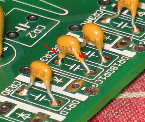
I'm thinking it's probably the change in my house's line voltage, cause I just checked it and it's 117.2 volts, and every other time I remember checking it it's been right around 120. I checked the bias of the DBs, and I've never had the cover on my amp (too lazy to drill all those holes, plus I love being able to see the inside of it). What are the PS smoothing caps, the little yellow ones b/t the 4 diodes behind the 'sink? I don't know why one of the solder joints would have come loose, but I guess it's worth checking...although I just remembered that I stressed one lead of one of em (if they are the PS smoothing caps) a little too much and cracked the casing when I was soldering them.
crackedcap.jpg
Maybe I'll get a new one of those with my next mouser order.
 

Users who are viewing this thread

Back
Top