


fongalv
100+ Head-Fier
- Joined
- Jan 17, 2005
- Posts
- 126
- Likes
- 10
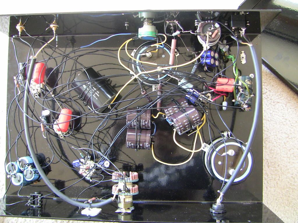
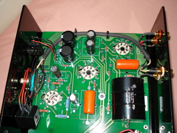
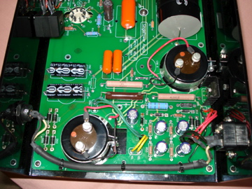
As I'm current away from home, I'm unable to take any images of the transformer, or the uncovered transformer for that matter since it will require me to unscrew the PCB.
I've spent the last few minutes comparing mine with mrarroyo's MPX3 and mine sports a similar transformer other than the fact that mine does not sport a spec label and wired for EU(220V).
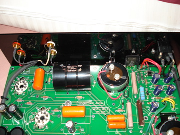
I understand the issues of the need for the bleeder resistors across the caps and the underspeced voltage switch(which would be more tricky to mod), but
since I'm not touching the large caps all the time, and neither am I fiddling with the voltage switch, I'm not that worried about them(unless they are exploding risks).
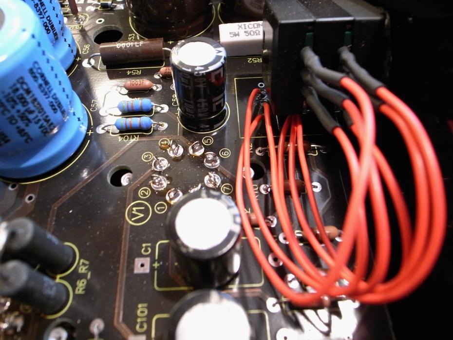
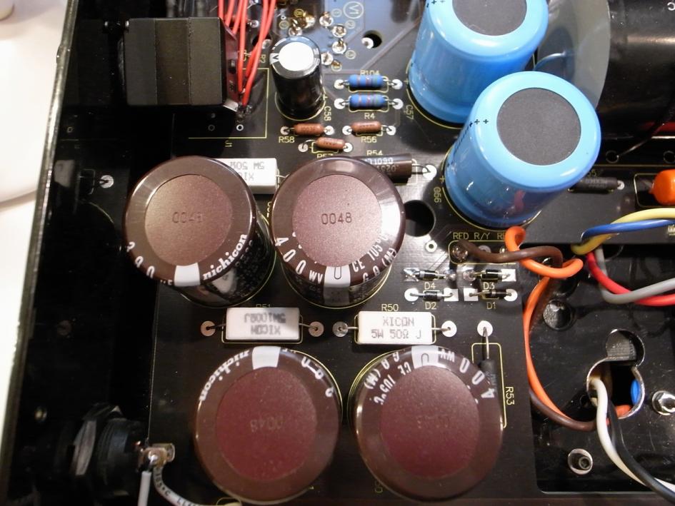
Shouldn't the main issue at hand be the danger of the "exploding amp" which after sifting through the thread is caused by the overheating of the filament/HV diodes by the wrongly spec'ed transformer/capacitors? If so and since mine does not sport any discoloration at all should I be concerned? As far as I remember, I'm running a 6SN7WGTA as input and 2X E182CC as output...
I guess the one consolation I got is that I'm currently off on a trip and have no chance of blowing my head off!
Edit: I just realised that of the 3 portable amps and 1 desktop amp that I own, all(three) of the makers have have ceased to exist...
I've spent the last few minutes comparing mine with mrarroyo's MPX3 and mine sports a similar transformer other than the fact that mine does not sport a spec label and wired for EU(220V).
I understand the issues of the need for the bleeder resistors across the caps and the underspeced voltage switch(which would be more tricky to mod), but
since I'm not touching the large caps all the time, and neither am I fiddling with the voltage switch, I'm not that worried about them(unless they are exploding risks).
Shouldn't the main issue at hand be the danger of the "exploding amp" which after sifting through the thread is caused by the overheating of the filament/HV diodes by the wrongly spec'ed transformer/capacitors? If so and since mine does not sport any discoloration at all should I be concerned? As far as I remember, I'm running a 6SN7WGTA as input and 2X E182CC as output...
I guess the one consolation I got is that I'm currently off on a trip and have no chance of blowing my head off!
Edit: I just realised that of the 3 portable amps and 1 desktop amp that I own, all(three) of the makers have have ceased to exist...