My Singlepower Supra Experience - Why mine almost blew up like a Hand Grenade (and yours might too)
Aug 13, 2009 at 6:29 PM Post #241 of 314
Quote:

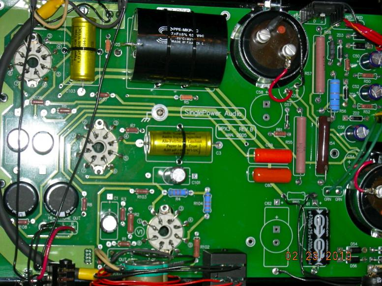
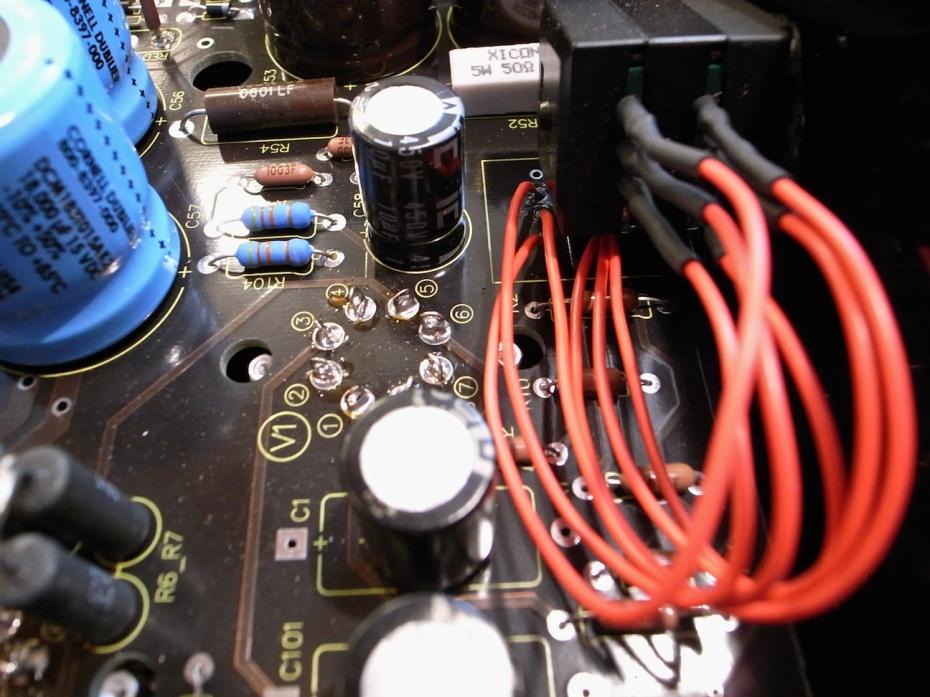
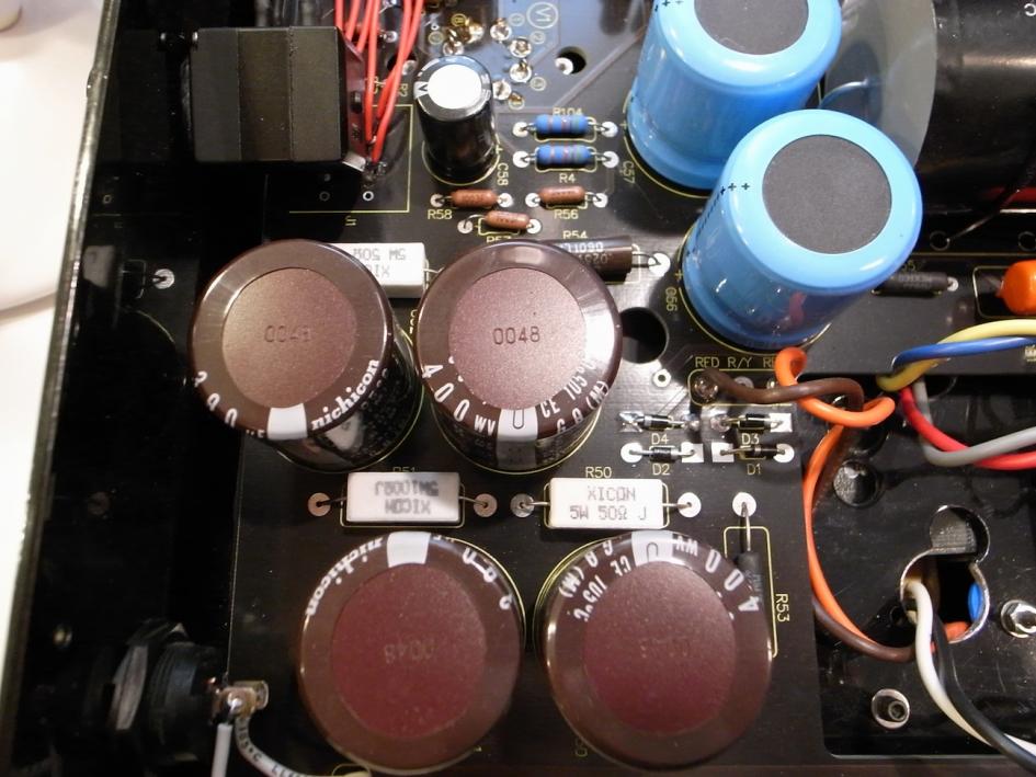
Originally Posted by Bolder /img/forum/go_quote.gif
Actually you should be fairly safe with the 6BL7/6BX7 as output tubes. They draw 1.5 amps each. It you use a 6SN7 as a driver, you would be pulling roughly 3.6 amps.

The 6AS7 draws 2.5 amps each. Using those tubes would possibly be a problem.

I would suggest that you consider completely disconnecting the switch and running the amp just off the regulated 260 V. Dr. Gilmore's simulations show much poorer performance at the higher voltage. The HV doesn't benefit anything and that switch could still fail.

See what diodes are in your unit. The diodes in Tyson's are only rated to 1,000 volts and 3 amps. Turn on surge from trying to fill the big caps peak at well above that rating. The same diodes are used in the filament circuit. I think you would want to use something at least double those ratings.


Thanks again. Yes, I like the 6SN7GT as an output tube. That's what you mean by driver? Or did you mean input tube?

OK I will check, but help me find them, please....and thanks again. I peaked in today and wasn't sure what I was looking at.

I need to see if I can hear the difference between high and low power. I have never listened to the difference.
 
Aug 13, 2009 at 8:34 PM Post #242 of 314
Quote:

Originally Posted by Frihed89 /img/forum/go_quote.gif
Thanks again. Yes, I like the 6SN7GT as an output tube. That's what you mean by driver? Or did you mean input tube?


Driver = input, at least typically.
 
Aug 15, 2009 at 9:00 PM Post #243 of 314
Can someone point to the rectifier diodes, please, so I can check to see how they are rated?

3792433647_6c966a8459.jpg


Thanks.
 
Aug 15, 2009 at 9:06 PM Post #244 of 314
filament diodes ----- the four big black diodes near the power
switch.

high voltage diodes---- the pair of diodes next to each other
about 1 inch from the back of the board, and about 1.5 inch from
the bottom edge of the board. under the red wires and lower right
from the orange drop.

frihed.jpg
 
Aug 17, 2009 at 2:22 PM Post #246 of 314
Quote:

Originally Posted by kevin gilmore /img/forum/go_quote.gif
filament diodes ----- the four big black diodes near the power
switch.

high voltage diodes---- the pair of diodes next to each other
about 1 inch from the back of the board, and about 1.5 inch from
the bottom edge of the board. under the red wires and lower right
from the orange drop.


Thanks very much.
 
Aug 17, 2009 at 2:25 PM Post #247 of 314
Quote:

Originally Posted by mrarroyo /img/forum/go_quote.gif
Kevin, any place where I could source four of those diodes (same shape) rated at 25 amps? BTW, at what voltage? Thanks again.


Thanks for asking the question, Miguel.

As a side note (you can PM me), do you know if this CANJAM thing is going to come off, or not? The RMAF folks are very excited and seem to have allocated a lot of space, but last time I looked (often) none of the mfrs. had signed up.
 
Aug 17, 2009 at 3:28 PM Post #249 of 314
diodes that get that hot are being pushed way over their specifications.
That has nothing to do with the transformer.
 
Aug 17, 2009 at 3:55 PM Post #251 of 314
Quote:

Originally Posted by mrarroyo /img/forum/go_quote.gif
Kevin, any place where I could source four of those diodes (same shape) rated at 25 amps? BTW, at what voltage? Thanks again.


Have a look here. DIOTEC ELECTRONICS CORPORATION MANUFACTURES TVS DIODES FOR PoE SURGE PROTECTION,SOFT RECOVERY HIGH SPEED LEAD MOUNT/TAB MOUNT/BUTTON DIODES AND RECTIFIERS, PRESS FIT DIODES, DIODE CELLS, AND MORE

Maybe Dr Gilmore can suggest a good alternative from the many models these guys produce.

Peete.
 
Aug 17, 2009 at 4:06 PM Post #252 of 314
i like the 35a lead mount diodes. Only thing is the diameter of the
wire may not fit in the circuit board.

And actually the 8 amp bridge can be coaxed into there with a bit
of bending.
 
Aug 18, 2009 at 2:25 AM Post #253 of 314
Quote:

Originally Posted by kevin gilmore /img/forum/go_quote.gif
i like the 35a lead mount diodes. Only thing is the diameter of the
wire may not fit in the circuit board.

And actually the 8 amp bridge can be coaxed into there with a bit
of bending.


Kevin, electronics is not my thing so sorry for the newby question. The 8 amp bridge has 3 legs, so how do I make it fit when the diodes in my MPX3 have two legs.
redface.gif


BTW, does the 6BL7 uses 2.5 amps or 1.5 amps? I have been told both numbers and I am confused. Thanks.
 
Aug 18, 2009 at 10:30 AM Post #255 of 314
The 8 amp bridge has 4 wires. A plus wire, a minus wire, and 2 ac wires.

So the plus wire goes to either of the 2 anode connections pointing to the
inside of the chassis, the minus wire goes to either of the 2 cathode
connections at the outer edge of the chassis and the AC wires, one
goes to the front junction of the 2 diodes, and the other goes to the
back junction of the 2 diodes.

like this

singlepowerdiodes.jpg
 

Users who are viewing this thread

Back
Top