


what is the model of that equipment and how much does something like that cost?
You are using an out of date browser. It may not display this or other websites correctly.
You should upgrade or use an alternative browser.
You should upgrade or use an alternative browser.
My DIY electrostatic headphones
- Thread starter chinsettawong
- Start date
Here is my progress so far building the headphones and stators:
chinsettawong
Headphoneus Supremus
Here is my progress so far building the headphones and stators:
Nice video! What is your spacer's thickness? It looks to be pretty thick. Is it 1 mm? What amp are you making?
For thick spacers, using a heat gun to shrink the diaphragm is OK. But if you go down in thickness, you'll need a lot more tension on the diaphragm and heat shrinking won't be sufficient.
Keep us posted with your progress.
")
chinsettawong
Headphoneus Supremus
what is the model of that equipment and how much does something like that cost?
I bought it from here: https://www.minidsp.com/products/acoustic-measurement/ears-headphone-jig
Nice video! What is your spacer's thickness? It looks to be pretty thick. Is it 1 mm? What amp are you making?
For thick spacers, using a heat gun to shrink the diaphragm is OK. But if you go down in thickness, you'll need a lot more tension on the diaphragm and heat shrinking won't be sufficient.
Keep us posted with your progress.
Thanks - this is great info.
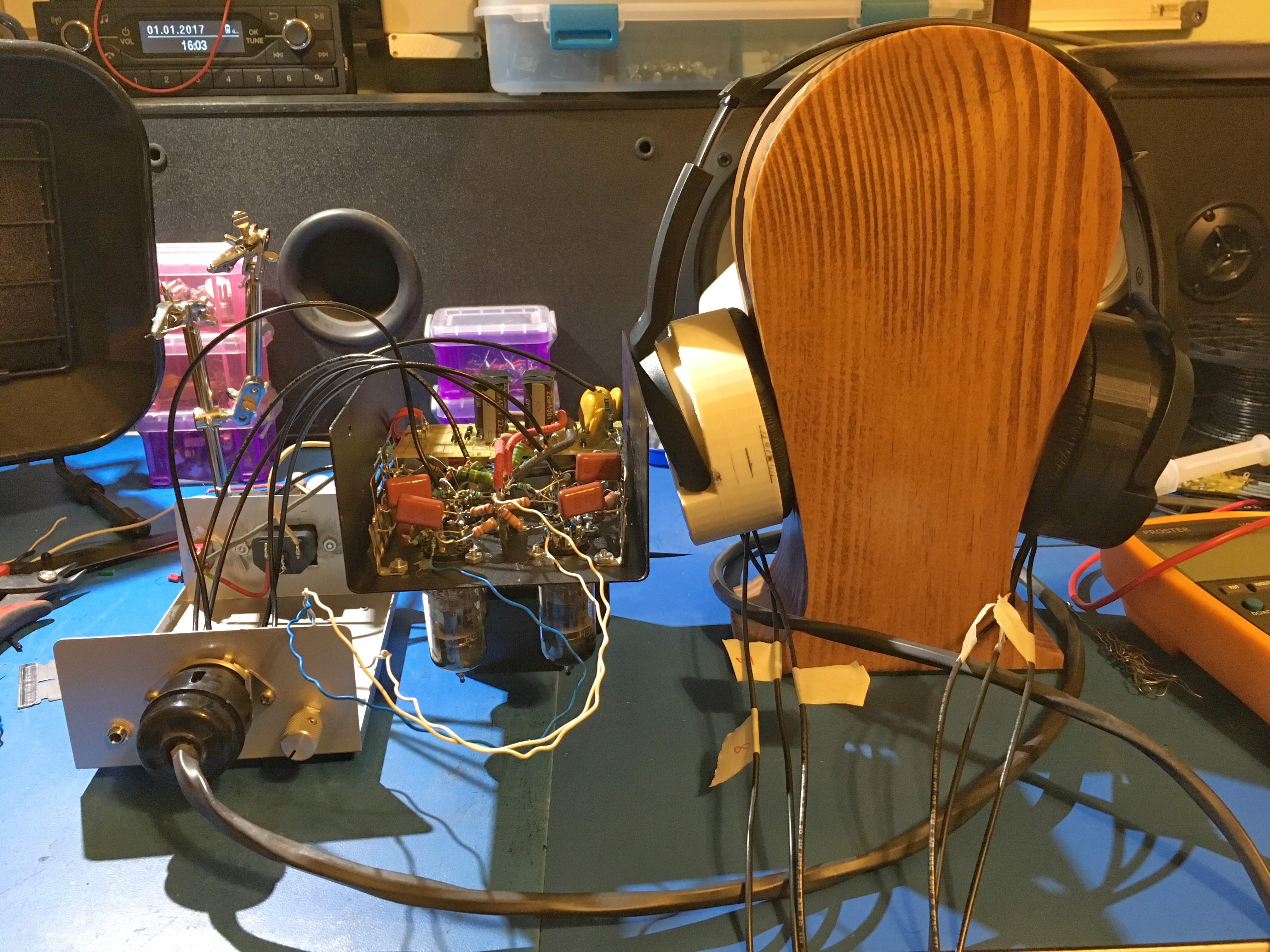
Spacer thickness is PCB width so 1.6mm.... i have on order a 0.6mm version.. still experimenting. I did not know that heat shrunk may be too loose.. Will find out if I have arcing with the 0.6mm version.. The amp is a modified version of what your original post was. Instead of using an xformer for the bias I am using a voltage doubler off a 310V tap referenced to GND. Using a negative bias since ive been told the negative ions are healthier (haven’t researched it much). For output tube I’m using a 12at7.. Also added some negative feedback so for a 0.55V amplitude input the output will have max swing. attached are some prelim pics of the amp
Attachments


Last edited:
Just got done with the first prototype build and it sounds good. I had an issue with buzz on my amp and so I put in a humdinger (two 500ohm resistors in series across the heater the tie that center tap to GND so the heater to cathode now has a reference). Buzz is caused by heater to cathode leakage current. Then there is a very slight low and calm 60Hz hum now caused by battery ripple. Not noticeable when playing music. I can make it 100% quiet by placing a bigger output cap but there is simply no room in the chassis.... Not concerned though. Hope this helps anyone with hum or buzz issues.
Attachments
Last edited:
chinsettawong
Headphoneus Supremus
Have you changed your spacers to thinner ones yet? Are you sure that the noise isn’t from the phones?
Have you changed your spacers to thinner ones yet? Are you sure that the noise isn’t from the phones?
Yup they are 0.4mm now with -700V bias. Buzz was def caused by heater to cathode leakage - fixed with a humdinger like I discribed. Buzz is always heater cathode leakage. Hum is different. The very quiet hum can be completely removed with larger output caps on the +B but like is said my chassis is too small. But it doesn’t bother me because it is so quiet anyway. I have a 6.8k grid stop resistors on the input so I never have issues with noise pickup on the input. I adjusted the cathode bias to make sure they are both as balanced as possible at the center point (0V) to get max output swing. Loudness is excellent. I can post my schematic once I get it updated.
chinsettawong
Headphoneus Supremus
With 0.4mm and -700V bias voltage, your diaphragm tension must be very high. How did you tension your diaphragms?
How do you tension yours? Any pics? I may need to learn how
Last edited:
chinsettawong
Headphoneus Supremus
It's amazing that you can hand stretch and heat shrink your diaphragm to the right tension. I use inner tire stretcher which I have posted pictures many, many times on this thread. Please check.
Thanks man - i'm working on reading the thread.. on page 47... It's pretty interesting.
Maybe I can see how much force it will take to displace the diaphragm.
Just an idea -but maybe I can make a solid state driver with FETs that have very high headroom maybe +/-400V... and put in some active filter and create a bass boost... or a baxendall equalizer...
May be cheating but it may work also for deeper bass.
Last edited:
bui501-tech
Head-Fier
- Joined
- May 1, 2016
- Posts
- 52
- Likes
- 35
It's so great and inspiring to hear the different methods and materials that all the DIYers on this forum use to design and build their working electrostatic headphones.
I've experimented with different materials for the membrane prior to settling on the more "traditional" mylar that chinsettawong uses. shrinkwrap, model airplane membrane, etc -- none of them would work. I've never heard of the heat-shrinkable mylar you're using. q1en, would you mind sharing the source (vendor) for the heat-shrinkable mylar if you can get the info from your friend who provided you your mylar?
I've experimented with different materials for the membrane prior to settling on the more "traditional" mylar that chinsettawong uses. shrinkwrap, model airplane membrane, etc -- none of them would work. I've never heard of the heat-shrinkable mylar you're using. q1en, would you mind sharing the source (vendor) for the heat-shrinkable mylar if you can get the info from your friend who provided you your mylar?
100VoltTube
100+ Head-Fier
- Joined
- Jul 29, 2016
- Posts
- 229
- Likes
- 39
I finally finished my headphones today. I'm listening to them now. They sound pretty great, but have very little bass. I'm assuming that the tension is just too high. Would heating up the diaphragms reduce the tension?
Also, the dust covers crinkle whenever I move my head. They're 3um mylar the was crumpled up. Is this normal?
Edit: actually, the lack of bass was because of series resistors in the transformer box. Time to save up to make a proper electrostatic amp.
Also, the dust covers crinkle whenever I move my head. They're 3um mylar the was crumpled up. Is this normal?
Edit: actually, the lack of bass was because of series resistors in the transformer box. Time to save up to make a proper electrostatic amp.
Last edited:
I finally finished my headphones today. I'm listening to them now. They sound pretty great, but have very little bass. I'm assuming that the tension is just too high. Would heating up the diaphragms reduce the tension?
Also, the dust covers crinkle whenever I move my head. They're 3um mylar the was crumpled up. Is this normal?
Edit: actually, the lack of bass was because of series resistors in the transformer box. Time to save up to make a proper electrostatic amp.
Ok good. I was going to say, headphones should be fine and check your amp but I thought you said you use a STAX amp. Is the transformer the power transformer or does it use an audio transformer? If it's a power xformer then you can probably increase the capacitance to get the proper cutoff. What is up with your dust cover? Can you send a pic? Why do you want a crinkly thing on your headphones? lol
Users who are viewing this thread
Total: 6 (members: 0, guests: 6)
