Musical Paradise M2-D2 AK4490 Balanced Dac Reviews?
Oct 24, 2017 at 8:46 AM Post #196 of 964
I use Jupiter caps which are pretty big but fit. I think Audyn should fit.
Caps Jupiter 4,7, my DAC does not fit (the top cover is not closed), and 2,2 Audyn more in size .
4.7uF 600V Jupiter HT - Body dimensions: 45mm (diameter) x 60mm (length)
2.2uF 630Vdc Audyn Cap True Copper Max - Body dimensions: 65mm (diameter) x 60mm (length)
 

Attachments

  • IMG_20170324_220825.jpg
    IMG_20170324_220825.jpg
    1.3 MB · Views: 0
  • IMG_20170324_213636.jpg
    IMG_20170324_213636.jpg
    1.3 MB · Views: 0
Oct 30, 2017 at 9:11 AM Post #198 of 964
Today the following rectifier tubes arrived - GEC U52, Mullard GZ37 (newer tube from the 60s), Sylvania 5Y3GT. On the 6DJ8 tubes, the following arrived - Mullard CV2493 (from the 70s), Amperex 6922, RTC E188CC (made by Mullard).

I am expecting a few more rectifier tubes to arrive later this week.

I put in the GEC U52 immediately and listening to it now. I will give my feedback later.

Tube rolling is so much fun with the MP-D2 MkII.
Alan
 
Oct 31, 2017 at 7:41 AM Post #199 of 964
GEC U52, Mullard GZ37 (skinny bottle), Sylvania 5Y3GT

Rolling the above rectifier tubes is going to take a long time. I listen to a few hours of each of them and they do not sound at first too good to me. I think this is because of the tube being new and need a lot of burn-in time. Probably need 50-100 hours on each of them.
I guess that a proper shootout will not take place until all them them has been burn-in properly. I have a few more rectifier tubes coming and hopefully will arrive soon.

Alan
 
Nov 1, 2017 at 8:27 AM Post #201 of 964
1641_rectifier.JPG

Today, 3 other rectifier tubes arrived. They are 1641 (see the photo), 5852 Bendix (rugged 6x5) , 1274 Bendix (6x5) .

The 1641 makes the music sound very strong. Update on that later.

Alan
What are you using caps - 2.2uF 500V PIO Capacitors K75-10 ??? What is the sound of these caps compared to the other ?
12795475_1716771181901563_7144036989487750404_n.jpg
 
Nov 1, 2017 at 9:05 AM Post #202 of 964
Yes, it is K75-10 caps. Those are 6.8uf. Those are rated as 250AC, so it is sufficiently safe.

I bypass it with K40Y-9 0.015uf 600V. The sound is good and needs a lot of break-in time. These are PIO and mellow with tube very well.

I notice you are using 2C51 (5670). Have you compare them with E88CC ? How does it compare ?
 
Last edited:
Nov 6, 2017 at 4:57 AM Post #203 of 964
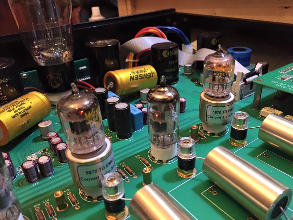
I have been studying the working parameters of the tube stage of MP-D2 Mk 2 for some time. The output stage of the MP-D2 Mk2 is basically an SRPP output stage. One tube for the DAC + output and one tube for the DAC - output thus forming a balance output. (for 2 channesl, you have 4 tubes). The B+ for the SRPP output tubes is at about 400V. So each section of the tube see about 200V.

The ES9038Pro DAC has an voltage offset of about 1.6V going to the SRPP tube. To deal with these voltage offset, the SRPP tube output stage has a cathode resistor of 10K. The resistor between each section of the tube is also at 10K. If you use the stock 6h6 tube, the standing voltage at the cathode of the tube is at 11V. So the standing current of the SRPP tube is 11/10,000 which is at 1.1mA. If you upgrade the tube to 6dj8/E88CC. The standing voltage at the cathode will be a 7.3V. Thus the standing current (bias current) is at 0.73mA.

The output tube working parameters are designed very conservatively. For the 6dj8 running at 200V with 0.73mA, each section is running close to 0.15W. The rated power of each section of 6dj8 is at about 1.5W. The sound of MP-D2 Mk2 with 6dj8 is very tubey, very gentle and beautiful. But I want it to sound more punchy and more body weight for rock and classical music. So I did the following modification.

The modification is to change the cathode resistor (10K in value) and the resistor between the tube sections (10K in value) of the SRPP tube. I am using single end, so I change only these 2 resistors for each channel. Thus 4x resistors in total for both channels. These 4 resistor are R13, R14, R21, R22. Instead of changing these 4 resistors, I piggyback a 4.7K (0.5-1w rating) resistor on each of these resistors. (So you don't have to take anything apart, just solder a resistor on top. so easy). The resulting resistance of the cathode resistor is now at about 3.2K.

As you are now consuming more current, the voltage drop on the power supply will be increasing. To counter this increase of voltage drop, I reduce the resistance of R6 from 20K to 15K by piggyback a 50K (5w) resistor on top the R6. In total, I piggyback 4x (4.7K) resistor and 1x (50K 5w) resistor. The resulting working parameter is, B+ is running at about 390V and the voltage at the cathode of the bottom SRPP tube is at 6.6V. Thus the current is about 6.6/3.2K which is about 2mA. Each section of the tube is now running at about 190V and 2mA. Each section is now consuming close to 0.4W.

The listening result as expected is that the music is much more punchy, powerful and more body weight.

Alan
 
Nov 7, 2017 at 12:23 PM Post #204 of 964
Why you need 4 tubes installed even you may be using only 2 tubes for single end output ? And how to overcome this constrain.

There are 2 reasons for this. And you need to address both of these or else you risk damaging your DAC or the tube or both.

Reason One: To provide suitable B+ voltage for the output tube. The power supply is designed to supply a B+ of 400 Volts to the Tube. Each output tube is designed to draw about 1mA of current. So for 4 tubes, the whole system draw about 4 to 4.5mA of current. The component of the power supply goes like this. Transformer supplying 400-0-400 AC output. It go through the rectifier tube which turns it to DC. The DC immediately go through an RC (resistor Capacitor) to smooth and drop the voltage to the desired voltage. This resistor is R6 and it is 20K Ohm and about 5W in rating. The capaictor is 150uf with 450V rating. It is important the R6 cause a drop of voltage to below 450V or else the capacitor will be fried. With 20K ohms and with a current draw of 4-4.5mA, R6 will cause a drop of voltage of 20K * .0045 = 90 volt. The Voltage after rectification is about 500V. Droping a 90V by this RC will make the voltage to go 410V which is safe for the capacitor.

After this RC, there is an LC which further dropp the Voltage slightly, and then there is a split to form another RC for the left Channel and another RC for the Right Channel. These 2 split RC use only a resistor of 1.5K which the purpose is to give a separate supply of B+ to the left and right channel.

What if, if you take out the non used tube and keep only the one used for single end. You change the parameter of this working power supply. Instead of consumming 4.5mA, you are only consumming 2mA. The R6 Resistor cause a drop of voltage of 20k x 2mA which is only 40V. You now has a B+ of 460V which EXCEEDED the rating of the capacitor of only 450V. If you take away the other non-used tube, you risk by shorting the life of the power supply and of course the capacitor will fail soon.

One way to solve this problem is increase the current bias of the single tube by at least a double (see my above notes about increasing the bias current of the tube and why I want that).

Reason Two: The Filament voltage has to stay at around 6.3V. The filament of these small tube are supplied by DC. The value of voltage goes through some sort of RC resistor capacitor such that the drop of filament voltage will be just correct when you have 4 tubes using. If you have only 2 tubes, the filament voltage goes up to 7.6V and your 6dj8 will very soon die.

Suddenly I have this idea to solve this issue. First I increase the bias current of the tube to 2-3mA which allow me to uninstall the other tube. And for the tube, I can use an 7DJ8 instead of 6DJ8. 7DJ8 use 7.6V filament. I can now totally get rid of the other no use tube and my goal of just puting in the component that is need to work to work. This reduce the amount of components that are not needed.

Also 7dj8 is in generally lower cost than 6dj8. I will certain keep exploring this tube rolling approach.
 
Last edited:
Nov 8, 2017 at 10:22 AM Post #205 of 964
There are bascially inifinte combination you can change to tweak the sound coming out from the DAC. The output cap is one area of them. There are many reasons the manufacturer put in the specific output cap. Apart from the technical requirement other reasons include such as available of parts (long terms, short term), cost of parts (whicn include this capacitor), synergies with other components, combination of the systems, ...etc. and possibliy a combination of a few of these.

In terms of technical requirement, the output of the tube circuitry usual go through an RC (capacitor coupled) which block off the DC on the tube supply. So what value of the output cap you need? Theoretical the required C and R you can use the formula fc = 1 / ( 2*PI*C*R). I checked that the resistor (couple the output cap to the ground) in my MP-D2 mkII is about 500K. Outpu cap of 1uf is plenty of juice to keep your output to less than 1Hz.

OK, this hobby is not about theories. I don't buy that either. That is why Music Paradise give you the options to change different caps (and including different values within the technical requirement) so that you can taste music differently. And kudos to MP for giving us this option. (MP wants you to tastes different caps) And thinking that the supplied cap is the best option is really not logical given there are literally thousands of caps on the market that satisfied the technical requirement.

It is impossible to hear all of them but I can taste the joy of rolling a few different caps.

Alan

I also have question about the values of cap, and here's a reply from Garry:

Me:
What is the sonic impact on using different coupling capacitor value (e.g. 1.5uf Vs 2.2uf Vs 3.7) ? or if there is any.
Garry:
If your amp input impedance is 5K-8K, using a 1.5uf coupling caps would have less deep bass. Most of amps are 47K-100K input, so 1.5-4.7uf are fine.

Me:
The reason I am asking is ,I am looking at rolling the 2 caps with Jupiter Copper. It cost more for 2.2uf than 1.5uf. And if there's no impact on sounding, it might be more reasonable to pick 1.5uf. Or if you think there are reasons for choosing higher uf value
Garry:
Depending on your amp input impedance, you need to measure it to confirm. 2.2uf usually provides deeper bass response if your amp input impedance is lower than 50K.

Me:
My amp is MP 501, so what's the impedance. Or does it also depends on the tube I use?
Garry:
MP-501 is 100K. 1.5uf is fine. Not related to tubes.

*************
For Jupiter Copper Foil it cost $35 more on each of 2.2uf over 1.5 uf.
(for some other caps, cost difference might not be as significant among cap values)
Beside, the size of the cap to fit in the space matters as well.

My impression to Jupiter copper is I think it got almost everything you need to be a decent cap.

I also tried the Jantzen Superior Z-Cap 2.2uf. I would say it's lateral from the stock cap rather than an upgrade which is more on the neutral and balance sounding. Depends on your preference. It's not the same big WOW over the stock cap as I replace with Jupiter.

***Reminder: All caps should be at least 450 VDC
For those who might not know, here's a caps shoot-out with good review among caps:
http://www.humblehomemadehifi.com/Cap.html
 
Last edited:
Nov 8, 2017 at 12:23 PM Post #206 of 964
Gary's advice is spot on. You can use 1.5uf or 2.2uf.

As my pre-amp has got an 100K input impedance , I am using 1uf 630V Jenzen Copper foil Copper tube. My system bass response is plentiful.

Alan
 
Last edited:
Nov 8, 2017 at 1:40 PM Post #207 of 964
.......

The modification is to change the cathode resistor (10K in value) and the resistor between the tube sections (10K in value) of the SRPP tube. I am using single end, so I change only these 2 resistors for each channel. Thus 4x resistors in total for both channels. These 4 resistor are R13, R14, R21, R22. Instead of changing these 4 resistors, I piggyback a 4.7K (0.5-1w rating) resistor on each of these resistors. (So you don't have to take anything apart, just solder a resistor on top. so easy). The resulting resistance of the cathode resistor is now at about 3.2K.

As you are now consuming more current, the voltage drop on the power supply will be increasing. To counter this increase of voltage drop, I reduce the resistance of R6 from 20K to 15K by piggyback a 50K (5w) resistor on top the R6. In total, I piggyback 4x (4.7K) resistor and 1x (50K 5w) resistor. The resulting working parameter is, B+ is running at about 390V and the voltage at the cathode of the bottom SRPP tube is at 6.6V. Thus the current is about 6.6/3.2K which is about 2mA. Each section of the tube is now running at about 190V and 2mA. Each section is now consuming close to 0.4W.

The listening result as expected is that the music is much more punchy, powerful and more body weight.

Alan

Interesting mod. I know nothing about electronic, but I might consider doing the same.
Does quality of resistor matter? Do they have polarity?
 
Nov 8, 2017 at 10:33 PM Post #208 of 964
The resistors do not have polarity. Quality does matter. I am using AMRG resistors for R21,R22, R13, R14. (0.75 watt version will do). For R6, I am using normal wire round 5W resistor.

Suggest you get someone that knows how to use a solder iron to do this. Also make sure you have all 4 tubes in place when using the DAC.
Cheers.
Alan
 
Nov 9, 2017 at 10:36 AM Post #210 of 964
The resistors do not have polarity. Quality does matter. I am using AMRG resistors for R21,R22, R13, R14. (0.75 watt version will do). For R6, I am using normal wire round 5W resistor.

Suggest you get someone that knows how to use a solder iron to do this. Also make sure you have all 4 tubes in place when using the DAC.
Cheers.
Alan

I see. Can you please clarify: "For R6, I am using normal wire round 5W resistor." Does that mean a 50K, 5W? what about 51K, 5W or 47K 5W, where I have access to?

Yes, I can do soldering as long as there's clear instruction. It's just that I do not have circuit knowledge. In fact, I am thinking of upgrade my D2 to MK2 version, which Garry can offer a half-finish MK2 board, for me to DIY upgrading. Then, I can do your mod at the same time.
 

Users who are viewing this thread

Back
Top