Modding the Sony SCD-CE595
Apr 11, 2008 at 10:47 PM Post #76 of 93
Quote:

Originally Posted by Pacific Microsonics /img/forum/go_quote.gif
The reason the results were not "and upgrade" was because the mods are a bit flawed. The auricap in transformer pcb tweak is truly a "tweakers tweak" because the "power filtering" isn't really done at this stage and it is very possible the auricap tweak actually worsens things.


I agree, It seems like a somewhat odd place to add some caps, perhaps we will find a location that works better. That or an enhanced power supply for the DAC/output section.
 
Apr 12, 2008 at 3:24 AM Post #81 of 93
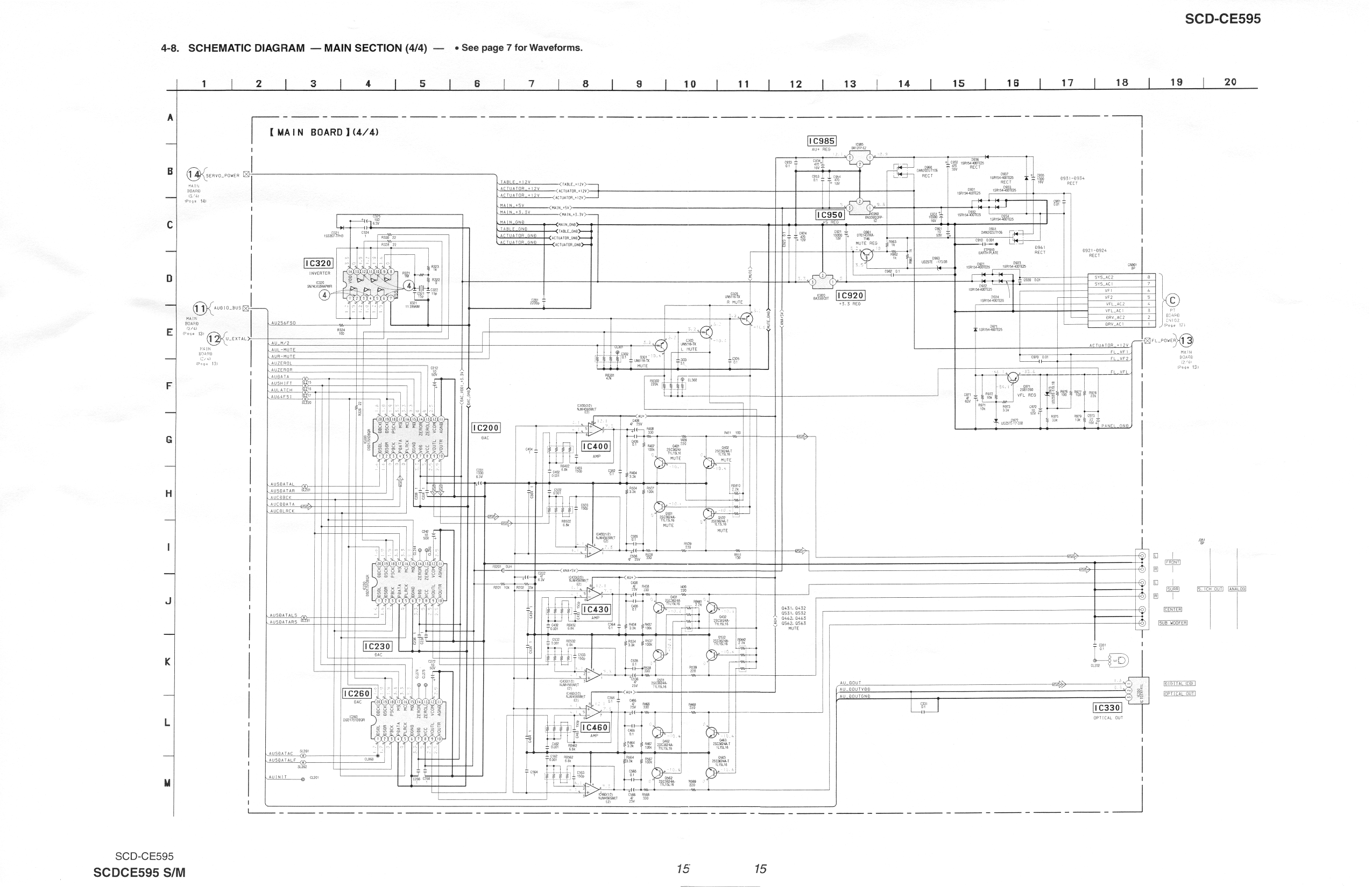
Yeah, looking at the schematic real quick, the same 3.3v and 5v regs power the motors and actuators as the dacs and opamps. Not a surprise, but just making sure.
 
Apr 12, 2008 at 4:01 AM Post #82 of 93
Quote:

Originally Posted by Gross /img/forum/go_quote.gif
the same 3.3v and 5v regs power the motors and actuators as the dacs and opamps.


if it is too hard to find the spot to seperate drive/digital/analog power, just cut off the traces at (dac and opamp) chips' power leads, and run wires directly from batteries to the chips, like a "star" power distribution if you will.
icon10.gif
 
Apr 12, 2008 at 6:14 PM Post #83 of 93
Quote:

Originally Posted by AudioCats /img/forum/go_quote.gif
if it is too hard to find the spot to seperate drive/digital/analog power, just cut off the traces at (dac and opamp) chips' power leads, and run wires directly from batteries to the chips, like a "star" power distribution if you will.
icon10.gif


Quote:

Originally Posted by AudioCats /img/forum/go_quote.gif
such as a couple of NimH battery boxes and an extra charging circuitry..... ;D


NOW we're talkin
wink.gif


It's a sad thing I let go of my baby stax because of the stubborn headband long ago, otherwise I would'a done some real work on that thing too :p I see your baby energizer's gone through a real metamorphosis
biggrin.gif
 
Apr 12, 2008 at 6:19 PM Post #84 of 93
Quote:

Originally Posted by Gross /img/forum/go_quote.gif
Yeah, looking at the schematic real quick, the same 3.3v and 5v regs power the motors and actuators as the dacs and opamps. Not a surprise, but just making sure.


frown.gif


Li-ion batteries could be a possibility for their small size and low impedance. I'm thinking cannibalize a few cheap ebay cell phone batteries for this. A proper charger will be the hard part :\
 
Apr 12, 2008 at 8:32 PM Post #85 of 93
Actually Li-ion charging is easy, there is no need to fill it to 100% capacity in a hurry, so we can just set a voltage cut off @ 4v, and charge the cells at a small current. Li-ion doesn't like over-charg and over drain ( a protection board wil solve the problem), other than that they are easy to handle.
The real problem with Li-ion is the voltage changes too much. Full charge @ 4.2v and fully drained @ 2.5v, that is 1.7v change or a 40% drop from the full charge. Also the 2.5v is lower than the needed 3.3v.

I wouldn't want to add regulators (which reduces the surge response) to battery packs.

Now if NimH, or better yet, Nicd is used, then 3 cells will give 4v at full charge and still have 3.6v at fully depletion, there is no need for regulation, probably work well enough for 3.3v points. for 5v points, 4 NiCd cells should work well.
since the CDP is stationary, you can add a simple fix voltage circuit to always fill packs to approx 80% of full capacity, I would use LM317's to keep the NiCd cell at 1.3~1.32v (so 4v for 3x pack, and 5.2v for 4x pack), add current limitor to make sure the cahrging current never exceed 0.2C even when the cells are fully depleted.

It is actually easier than it looks, but is there enough room inside the case?
 
Apr 12, 2008 at 8:40 PM Post #86 of 93
Quote:

Originally Posted by Pacific Microsonics /img/forum/go_quote.gif
It's a sad thing I let go of my baby stax because of the stubborn headband long ago


That was long ago, right? which means it is about time to get another set, right?
biggrin.gif


who needs 001 headbands anyway, they degrade the sound quite a bit. It is now the ear mold era, the custom ear mold route is the only way to go
biggrin.gif
 
Jul 31, 2008 at 4:53 PM Post #88 of 93
I've had a 595 for a couple of years, and I recently bought two more 595 refurbs to hack on. I just ordered a paper service manual from Sony which may take a couple weeks, but I would like to get started sooner. Can anyone post an image of the schematic, only in the vicinity of the DAC and output filter? Or a free source of the PDF version?

I generally prefer a current-output DAC since I can then avoid the internal opamp-itis by using an all-tube I/V converter circuit that I designed. So...I may consider making a separate DAC box with an different DSD DAC chip, with cleaned-up clock, and glorious triodes. Digital and clock interfaces only, and a separate PS. Might share if it works well and if anyone's interested.
 
Oct 21, 2008 at 5:49 PM Post #90 of 93
Hey guys, I performed the power supply tweak this weekend using Xicon Metalized Poly caps and noticed the improvement right away. I figured I’d be safe and use something fire and heat rated. I also performed the Swenson mod however I accidently used the polystyrene capacitors I had ordered to adjust my phono input on my pre-amp. They are 47pF 600V Polystyrene caps and I soldered them between 9/10 on IC200 directly to the stock RCA jacks. My pre-amp presents a 50K ohm input impedance. The sound is amazing for both SACD and RB CD but I have a question. If the range recommended is .47uF to 47uF is there any thing wrong with leaving these 47pF caps in place? Am I losing something or did I just luck out? Also these leads were much easier to solder onto the chip that those I see in the pictures at the beginning of this thread and I don’t have to worry about them moving around or being hot glued in place since they are so small.
 

Users who are viewing this thread

Back
Top