mrdon
500+ Head-Fier
- Joined
- Mar 23, 2005
- Posts
- 827
- Likes
- 11
This is a work in progress. Keep checking in for more updates.
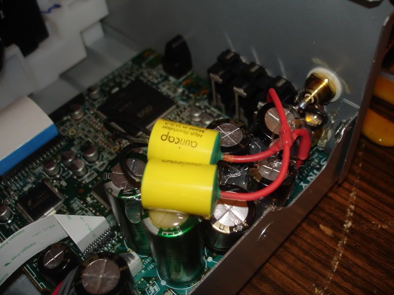
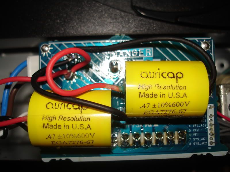
"Auricap Tweak" - This tweak provides tighter bass, less hash, really smooooths the music out. This is done by installing TWO .47 uF/600V Auricaps in parallel, with the red leads to the hot terminal and the black leads to the neutral terminal on top of the transformer pcb. This is at your own risk as Aurciaps are not safety rated. Nevertheless, this tweak has be performed by many with great results, with no disasters reported. Other brands of .47 uF/600V film caps can be used of course. They can be cheaper in price but they will not provide the same results as Auricaps IMHO.
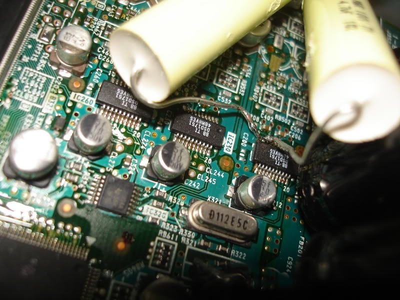
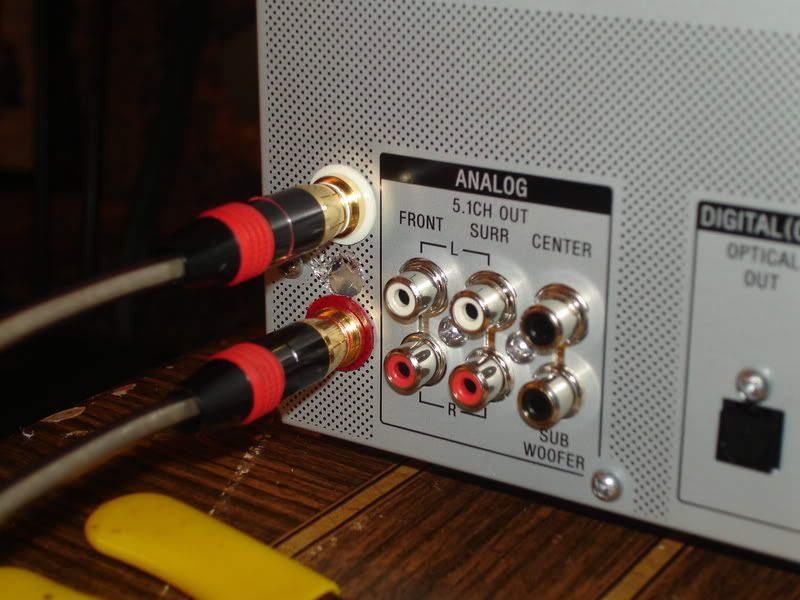
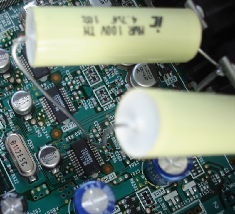
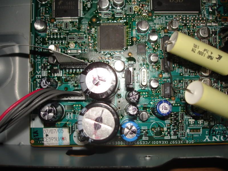
"Swenson Mod" - This modification removes the stock tizziness as compared to the stock opamp output stage. This can be done as the BB DSD 1751 is an output voltage DAC. This mod is performed by locating IC200 and carefully soldering one end of a film cap to pin 9 (Left channel) and another end of a film cap to pin 10 (right channel). The other ends are soldered directly to higher-quality chassis mounted female RCA's with the ground connected to the ground of the stock pcb mounted RCA's. What brand of film cap to use is up to you. Auricaps seem to be the preferred film caps of audiophiles these days but you can just as well use Solen's or Claritycaps. One thing is for sure. The leads of the film caps must be solid core wire and not stranded, because performing this mod is will be like trying to solder a rat tail on a flea. What size (uf/v) do you use? Voltage is minimal at this point in the circuit, so 100V and below will be fine. However, some premium caps come in much higher ranges. they will work but they will be very large. how about uf? Well, John Swenson (the originator of this mod) says "if you are feeding a preamp with a 50k input impedance a 0.47uf cap works well. If you are feeding a 10k preamp use a 4uf cap. For in-between input impedances choose a cap somewhere between 4 and 0.47." (BTW, The caps in the picture are Illinois MPW 4.7uf/100V are just temporary. B/c of their uf size, they are a little bass heavy, so the 1uf Auricaps are on order.)
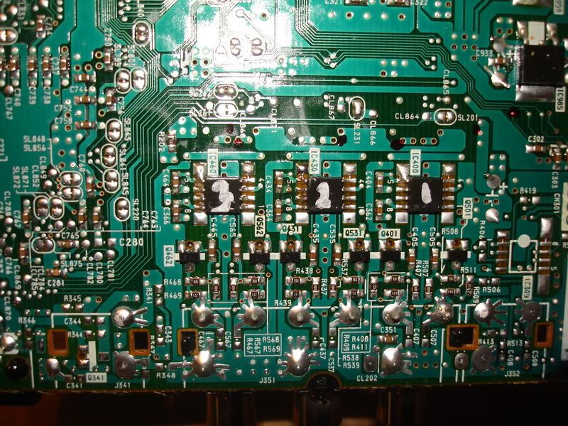
The other two-channel output stage mod - If soldering a rat tail on a flea is not for you, then you can replace you can replace IC400 located on the bottom of the pcb with the SOIC opamp of your choice. Be very careful with removal of the stock opamp or you will end up doing the Swenson Mod anyway.
Here's how head-fi member JunctionFET describes the exercise.
The 47uf/25V output SMD 'lytics should also be replaced. For two-channel these are numbers C406 and C506. They can be replaced with higher quality, better sounding 'lytics such as Black Gates, Panasonic FC, Elna Cerafine or Nichicon Muse KZ. (Note: Because this unit tends to be more on the bright side of neutral, I would suggest a warmer sounding 'lytic like Elna Cerafine or Nichicon Muse KZ.) To replace them, I offer you again fellow head-fi member JunctionFET's method.
NOTE: The solder used by Sony is tough stuff. In order to remove the 'lytics you need a really hot iron and some soderwick. Also, be careful as you can easily remove a solder pad while doing it.
More Later! Stay Tuned!
"Auricap Tweak" - This tweak provides tighter bass, less hash, really smooooths the music out. This is done by installing TWO .47 uF/600V Auricaps in parallel, with the red leads to the hot terminal and the black leads to the neutral terminal on top of the transformer pcb. This is at your own risk as Aurciaps are not safety rated. Nevertheless, this tweak has be performed by many with great results, with no disasters reported. Other brands of .47 uF/600V film caps can be used of course. They can be cheaper in price but they will not provide the same results as Auricaps IMHO.
"Swenson Mod" - This modification removes the stock tizziness as compared to the stock opamp output stage. This can be done as the BB DSD 1751 is an output voltage DAC. This mod is performed by locating IC200 and carefully soldering one end of a film cap to pin 9 (Left channel) and another end of a film cap to pin 10 (right channel). The other ends are soldered directly to higher-quality chassis mounted female RCA's with the ground connected to the ground of the stock pcb mounted RCA's. What brand of film cap to use is up to you. Auricaps seem to be the preferred film caps of audiophiles these days but you can just as well use Solen's or Claritycaps. One thing is for sure. The leads of the film caps must be solid core wire and not stranded, because performing this mod is will be like trying to solder a rat tail on a flea. What size (uf/v) do you use? Voltage is minimal at this point in the circuit, so 100V and below will be fine. However, some premium caps come in much higher ranges. they will work but they will be very large. how about uf? Well, John Swenson (the originator of this mod) says "if you are feeding a preamp with a 50k input impedance a 0.47uf cap works well. If you are feeding a 10k preamp use a 4uf cap. For in-between input impedances choose a cap somewhere between 4 and 0.47." (BTW, The caps in the picture are Illinois MPW 4.7uf/100V are just temporary. B/c of their uf size, they are a little bass heavy, so the 1uf Auricaps are on order.)
The other two-channel output stage mod - If soldering a rat tail on a flea is not for you, then you can replace you can replace IC400 located on the bottom of the pcb with the SOIC opamp of your choice. Be very careful with removal of the stock opamp or you will end up doing the Swenson Mod anyway.
Here's how head-fi member JunctionFET describes the exercise.
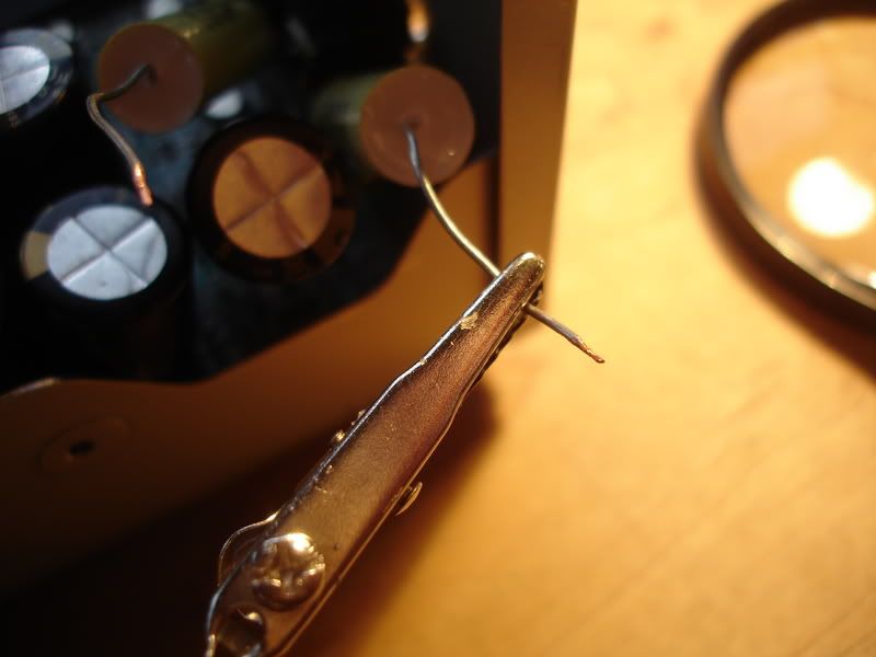
The opamps are located on the underside of the board. This mod is a bit tricky because you cannot actually remove the board from the player completely--you will be tethered by one set of wires that cannot be conveniently unplugged like the other connectors. It is not too big a deal though.
Once the board has been flipped over and is in a steady position, you can remove the opamp by very carefully clipping the tiny leads on the chip--there are 8 small leads in all. Be sure you have each one cut, then use some needle-nose pliers to remove the chip. If you have not cut through each lead completely, removing the chip may also lift or break a land.
Once the old chip has been removed, clean up the pads on the board with solder wick, then apply just a small amount of solder to each pad. Carefully place the chip in position--be sure to get pin 1 oriented correctly. Carefully and patiently use your iron to bond each lead quickly to each corresponding pad.
If you are in doubt about your ability, find an old circuit board with surface mount parts and practice some. You get only one shot at this on the CD player, so practice as much as you need to get it right. The recurring theme in all of this is to be careful... careful careful careful. And don't rush it, take your time. Don't bake the components with the iron though, use only enough heat exposure as is necessary to flow the solder. Surface mount stuff is really just tack soldering, and it only takes a moment to flow the solder sufficiently.
For anyone wanting to do this--use an opamp that is actually designed for audio, and do not use one of those insanely fast video opamps. Chances are a high speed opamp will oscillate, and once you install it on this board you will probably not be able to swap it out again without damaging the board--unless of course you are really good at swapping SOIC components on a mass-produced board. Also be sure to pick something that is indeed unity-gain stable.
The 47uf/25V output SMD 'lytics should also be replaced. For two-channel these are numbers C406 and C506. They can be replaced with higher quality, better sounding 'lytics such as Black Gates, Panasonic FC, Elna Cerafine or Nichicon Muse KZ. (Note: Because this unit tends to be more on the bright side of neutral, I would suggest a warmer sounding 'lytic like Elna Cerafine or Nichicon Muse KZ.) To replace them, I offer you again fellow head-fi member JunctionFET's method.
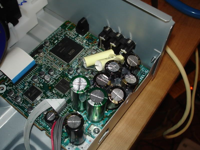
Other PCB components - Unfortunately, the board is primarily populated with surface mount caps, resistors, and diodes. IMHO, they are not worth messing with. But there are a small amount of through hole 'lytics that can be replaced with higher quality 'lytics (I used Nichicon MUSE KZ and FX.) I wish the capacitance could be increased by 100% on C-921 and C-931 and 20% on the others (ala Bob McNiece's "Tweaks for Geeks"), but the room on the pcb is very tight, and upgrading using stock sizes is really pushing it. BTW, here's the location and sizes needed.The output capacitors are easy to remove. We found it was easiest (and safest) to just pull the caps out of their leads/bases first. The surface mount caps they used are pretty cheesy, and the leads pull out really easily it seems. Once that is done, you can trim the leads back with the cutters and remove the bases. Some solder-wick can be used to carefully extract the remaining lead material from the pads on the board
Your new through-hole caps can be tack-soldered to the pads. Make sure you get the polarity right of course (negative side towards the output jacks). Trim the leads on the new caps so that they are not too long, but long enough that you can work beneath the caps with your iron. Bend the ends of the leads at a 90 degree angle to mimic a surface-mount lead. Melt a little solder on the lead ends and the pads. Line the cap up where it will go and one at a time use the iron to melt and flow the solder from each lead to each corresponding pad. Once the solder hardens, look over your work carefully to make sure it is stable and there are no solder bridges. Don't physically disturb the new caps too much because they will exert leverage on the board lands and could fatigue them.
Remember, when ordering the uF (capacitance) remains the same but the V (voltage) can go higher, not too much higher b/c of the space issue.C-971 47uF/63V
C-931 10,000uF/16V
C-921 10,000uF/10V
C-954 470uF/10V
C-924 470uF/10V
C-935 1000uF/16V
C-934 470uF/16V
C-201 1,000uF/6.3V
C-932 470uF/35V
NOTE: The solder used by Sony is tough stuff. In order to remove the 'lytics you need a really hot iron and some soderwick. Also, be careful as you can easily remove a solder pad while doing it.
More Later! Stay Tuned!