Mini Dac TDA1543 X 4 NOS
Jan 10, 2016 at 3:20 PM Post #961 of 1,063
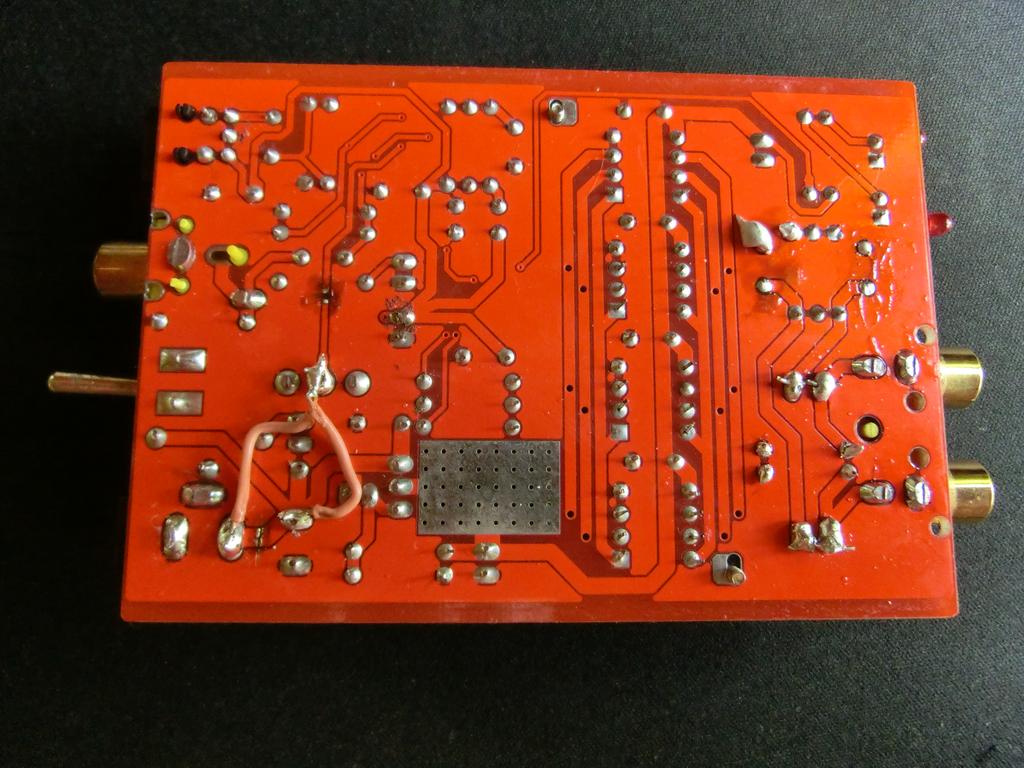
I don't know what PCB layout has to do with the colour. Colour means nothing since they change every batch or so. I've had blue, red and white PCB's for the same 4xTDA1543. You will have to give a technical description or a photo. The default I/V resistor value in the 4x1543 dac is 680 Ohms which is to much. That is the R between output and ground, right nezt to the RCA-out between the output caps (+get rid of those elco's those should never be in the output or input). Change the value to 460 Ohm and it will sound better with less (ie. without) clipping. But that is not as good as it can be. But for that you would have to read the whole thread.

If it is any other type of Muse dac I can't give you an answer because I don't bother with those. For a single TDA R-I/V would have to be 4x 460R, so; less than 2kR. But then it could just as well be something related to an opamp (yich!).
 
Jan 10, 2016 at 3:35 PM Post #962 of 1,063
I'm no expert in DAC modding, but after reading this thread, I've gotten quite interested in experimenting with different output caps and bypass caps.

A friend of mine helped me with the soldering and after a few iterations he went "why don't we just add swappable pins so you can just swap caps until you find the best combination."

I think it's a great idea, and maybe something for you all to consider, if you haven't already done so :)


I have the exact same one I came to see last week. It seems they ran out of cooler plates so they just used some spare end-plate with cutout holes. It looks ugly and is kind of silly. It would be far better to not heat it up so much with 8V (=Vmax).

But then so is using swappable pins. The point isn't the type or make or value of those parts but their place. Once you know the problem you will realize that swapping small 10uF caps is not the solution. And a fixed 1st order 15k LP filter is not desirable. The DAC can play 24/96 so why hardwire limit that at 15kHz?
 
Jan 21, 2016 at 10:49 PM Post #964 of 1,063
Hmm... Air? Gives the DAC more air in the highs.

I'm sorry if I'm not more helpful, but I spent a lot of time tweaking this unit. And I'm not giving it away for free anymore. Not just like that. Sorry if it is cryptic. I am selling mods and am about to make my own dac. So I don't do to many freebees anymore. I hope you understand. I have a clear vision of what I want and in another R2R thread I'm getting so much flac from 'objectivists' that always know better (but probably never actually made anything themselves) that I stick to hints.
 
Feb 3, 2016 at 7:54 AM Post #965 of 1,063
Can someone help with the I/V resistance calculation? So I have 9V PSU (linear stabilized) powering my muse, R1 is replaced to 470R, which gives me roughly 7V power on the output of LM317. I changed R10 and R11 resistors to 470R value, as recommended above. What about the VRef? Is R17 a VRef resistor? Which value for that one, and do I have to change it at all?
 
UDPATE: Discard that, I decided to look at the output on my scope and found that 460R with 7V gives you clipping, so I soldered trimming pots on top of R10, R11 and R17 and was able to set optimal values with maximum swing and guaranteed clipping free.
 
And yes, VRef is R17.
 
Jul 12, 2016 at 12:36 AM Post #968 of 1,063
has anyone done any mods to this, would like some reviews ;P. I found something similar but uses 6 tda 1543 and has usb only http://www.ebay.com/itm/HIFI-6X-TDA1543-Parallel-Fever-Audio-Decoder-DAC-PC-USB-External-Sound-Card-/131868348472?hash=item1eb3f75038:g:zj0AAOSwuzRXeyUS


I don't think those are TDA1543's. TDA1543's are DIP-8, those look like DIP-16 or some other 16 leg package. And why 6? I guess you can parallel as many as you want as long as you have the current and proper heat dissipation as well as the right input resistor.

My guess is that the existing supply of TDA1541's and 1543's is running a bit thin these days. Even the Mini-1543 DAC I have has one 1543 with slightly different printing on it than the others.

The only mods so far I have made with mine was remove he .1 uf caps just to the left of the output. The high end seems more, but also more splashy and almost harsh/fatiguing. I almost preferred those caps in place. I think I am going to replace it and the filter caps with better ones. I already have some MKP WIMA 22uf filter caps, I just haven't installed them yet.
 
Jul 26, 2016 at 10:16 AM Post #969 of 1,063
got this thing for cheap too.
 
it's the 15-18v version, and my conclusions so far are, that this DAC works best at 50% volume, and worst on 100% with shorted output caps + activated gain on my O2 at least, which has 1x and 2.5x gain.
Measured DC-offset is 3mV on my O2, with or without shorted output caps on the muse, BUT you could hear pretty severe popping with the shorted caps, when activating the gain-switch or turning it off(or switching between my crossfeed settings on the O2, but that's a different story: http://imgur.com/a/9J82a
tongue.gif
)
 
measured with RMAA:
with shorted outputcaps and volume at 100% + activated gain on O2, it has 6%!!! THD lol
without shorted output caps and volume at 100%, it has ~0.35% THD
without shorted output caps and volume at 50%, it has "only" ~0.08% THD
 
for reference: my soundblaster Z feeding the O2, has ~0.005 THD
 
now must listen further to the optimal setting, because non-optimal sounds very low-fi, as if you would blur over everything.
 
Jul 26, 2016 at 9:22 PM Post #970 of 1,063
got this thing for cheap too.

it's the 15-18v version, and my conclusions so far are, that this DAC works best at 50% volume, and worst on 100% with shorted output caps + activated gain on my O2 at least, which has 1x and 2.5x gain.
Measured DC-offset is 3mV on my O2, with or without shorted output caps on the muse, BUT you could hear pretty severe popping with the shorted caps, when activating the gain-switch or turning it off(or switching between my crossfeed settings on the O2, but that's a different story: http://imgur.com/a/9J82a :p )

measured with RMAA:
with shorted outputcaps and volume at 100% + activated gain on O2, it has 6%!!! THD lol
without shorted output caps and volume at 100%, it has ~0.35% THD
without shorted output caps and volume at 50%, it has "only" ~0.08% THD

for reference: my soundblaster Z feeding the O2, has ~0.005 THD

now must listen further to the optimal setting, because non-optimal sounds very low-fi, as if you would blur over everything.


What do you mean "shorted output caps"? Does that mean stock? Because when you say thatI imagine that cap is shorted across the leads, but that wouldn't work as you are shorting the signal to ground.

The higher THD than your Sound Blaster does not surprise me. With added DAC chips raises the THD more than an I/V and buffer would, but causes other issues (ringing I think). It's all about the transient response. Those stock output filter electrolytics are horrible though. I have some Wima MKS2's 10pf's ready to go if I can find the time.
 
Jul 27, 2016 at 10:10 AM Post #971 of 1,063
What do you mean "shorted output caps"? Does that mean stock? Because when you say thatI imagine that cap is shorted across the leads, but that wouldn't work as you are shorting the signal to ground.

The higher THD than your Sound Blaster does not surprise me. With added DAC chips raises the THD more than an I/V and buffer would, but causes other issues (ringing I think). It's all about the transient response. Those stock output filter electrolytics are horrible though. I have some Wima MKS2's 10pf's ready to go if I can find the time.

"shorted output caps"(C6, C7), was the #1 mod in this thread(if your amp had input caps, which protect from the DC-offset then instead).
 
10pF?
originals are 10uF(like 1 000 000 times of 10pF).
 
Since i don't need the coax-in, i misuse the switch as on/off-switch.
smile.gif


Jul 27, 2016 at 11:13 AM Post #972 of 1,063
"shorted output caps"(C6, C7), was the #1 mod in this thread(if your amp had input caps, which protect from the DC-offset then instead).

10pF?
originals are 10uF(like 1 000 000 times of 10pF).


I meant 10uF. The µ character to me always looks more like a "p", but "p" is actually pico, not micro. For Windows machines, it's Alt + 270 in case anyone is wondering how to type the µ (hold down Alt while typing 230 on the num pad).

The O2 does not have an input DC removal cap as you have found out as I too have an O2. Not sure on my Audio-gc C-2C.

Also, coax does sound better to me IMO. This goes for any DAC.
 
Jul 29, 2016 at 10:08 AM Post #973 of 1,063
So i use 9v power supply, r01 still at 510R which gives me 7V at the Chips nontheless, and reducing it to 6V had worse effects to the measurements.
Taking out the caps(C8/9) around the I/V resistors gave 0.02% higher IMD distortion, so i put them back.
 
now the interesting part:
 
I experimented with I/V resistors, and arrived here for now:
 
r17 = 390 to 172R
r10/11 = 680 to 150R
 
THD : down from 0.3% to 0.02%
IMD + noise: down from 0.3% to 0.03%
IMD + noise(swept freq): down form 0.25% to 0.045%
 
of course this is paid with lower output.
 
good part: "tizz" is still reduced compared to sigma delta(BTW, that can't be due to the rolled off highs, because i EQ'ed the FR-curve to use with the sigma delta, but nothing changed about "tizz" at all)
 
bad part: it still sounds blurry...
 
(i use a switchbox, and compare A/B within the same song, which takes only under a second to switch - volumes matched precisely by using RMAA -  don't wanna be victim of placebo!)
 
Aug 1, 2016 at 12:53 PM Post #974 of 1,063
Interesting to see this thread still alive, with more modding / testing / measurement
 
I was intrigued by the 0.02% you got, so I tried crocodile clips on just the I/V resistors (No space for the R_bias a.k.a R17) and got 0.04% with 468ohm (paralleled resistors) and a Windows volume of 68. Tried 278ohm and hit the DC voltage swing limit.
 
Looks like the problem is indeed the inability to swing AC voltage. With everything stock, 100% volume I got 0.23%, 80% gave 0.14%, and 56% gave 0.092%.
 
But since this isn't a real TDA1543, unless somebody knows what chip is being used, finding the best values is pure guesswork. The stock unit has a output V_bias of 3.85V and with that it can swing 2Vrms at 0dBFS. (Which, FWIW, cannot be achieved with a real TDA1543 @ 7.6Vcc) Which I guess is why they chose these values despite poorer THD performance.
 
Aug 1, 2016 at 1:36 PM Post #975 of 1,063
ah, you seem to have the same board as me(23€ incl. shipment from ebay
tongue.gif
).
TBH, i must have been kind of lucky with the low THD - at 1st i just added 390 Ohm in parallel to all of the I/V resistors, to achieve the values which were recommended for 4 chips in parallel.
After this showed good results, i was just adding 390 Ohm in parallel again, and this measured even better(of course it also means lower output) - then tried different values for R17(Vref), where i removed one of my paralleled 390 Ohm resistors, and replaced it with a 1.2kohm resistor.
 
This was basically just two tries with the R17, and now after trying a bit higher or lower than 172 Ohm for R17, it always measures worse than before.
BTW, by mistake i replaced the 2.2nf caps with 22nf ones, which has no bad effects it seems tho - only if i use the original I/V values it messes with the FR.
 
Well, electronics - still a mistery to me.
smile_phones.gif

 
But this device sounds addictive, even with its drawbacks when it comes to instrument separation.


oh, i always measured out of my O2 of course, otherwise i wouldn't get enough signal.
 
EDIT: made a mistake there, R10/11 is 200 Ohm not 150.
 
EDIT2: no it's not, 150 was and is right
rolleyes.gif


Users who are viewing this thread

Back
Top