b0bb
Headphoneus Supremus
- Joined
- Oct 15, 2014
- Posts
- 1,663
- Likes
- 888
1) Could you please clarify the modification proposed in post #18? I did not understand the transition before->after (pictures). Which WIMA polypropylene caps did you use? 63VDC 0,15µF MKP or FKP and what spacing (part number?)? How did you come up with the TX2575 249R00 0.05%? I did not find it in the Texas Components web shop. As you said, it is custom order only. Also a Y0706249R280T9L is hard to find in <1ku quantities. Are there equivalent or better quality alternatives which are easier to acquire?
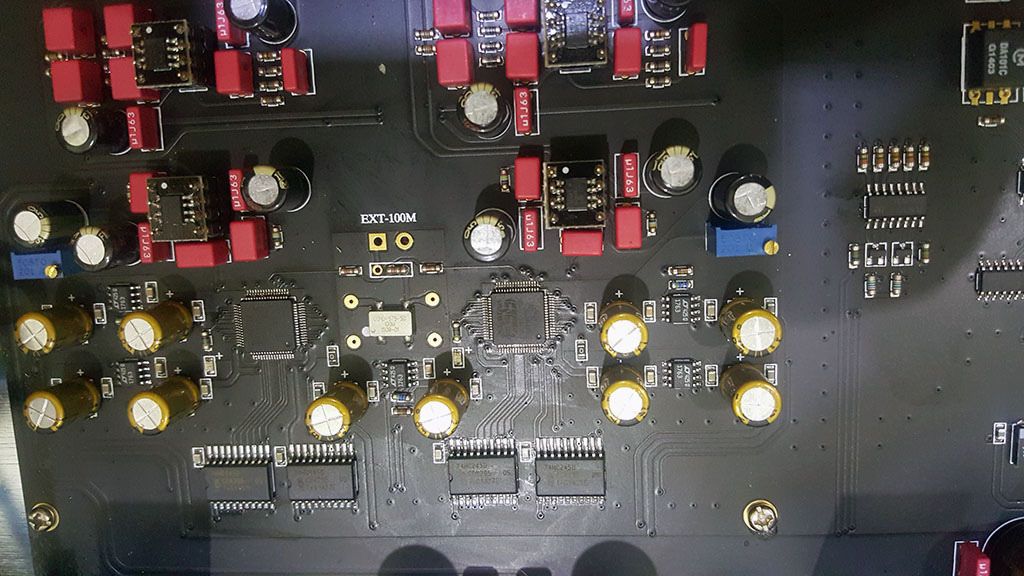
The caps are WIMA MKP2 5mm mounting pitch.
There are actually 3 bypass cap per supply rail
220pf Corning low-K CGW Glass Cap, 0.15 uF Wima MKP2 and the existing 100uF Panasonic FC
The CGW caps are Military surplus, you can also use Silvered Mica which Mouser and Digikey sells.
The TX2575 is the best component for the job. This is the resistor that converts the DAC output current to a working voltage. You have to remove the original surface mounted resistor on the top side of the board and mount the TX2575 to the underside of the board. The value can be read off the original resistor's color bands or it can be measured.
Contact Texas Components directly via email, the values are custom made at no extra charge about 12USD each.
2) Did you install the TPS7A4700 5V regulators from TekDevice (post #37) only on the digital side? Can you suggest an alternative (equivalent or better quality) which is easier to acquire and can be installed without reworking the connections/footprint?
The TPS7A4700 from Tekdevice is the only board that I could find in the form factor, it has to be kept very small to preserve the high-frequency performance and low noise, there are better regulators like the LT3042 but none in this small a formfactor board.
3) In post #44 you mention an Abracon ABLNO femto clock and "Sanyo OSCON-G" caps. What are the specs and part number of the "Sanyo OSCON-G" caps? If the part number is 16SA47M, what would be alternatives easier to acquire? Should these caps be installed only for the ABLNO clock or also for the Crystek CCHD-950X? Which of the two clocks do you prefer? Is there a significant audible difference?
The Abracon is significantly better, the OSCON-G is not being made anymore 16SA47M is the correct partnumber. The Original Nichicon Muse FGs are not good enough for this type of application
4) Why did you use 14-pin as a socket connection for the crystal oscillator? What are the spacings/diameters? Can you recommend specific parts (part numbers)?
It is a standard 14pin DIP with the unused pins removed, socket allows for swapping and trying out different types of crystals.
http://www.digikey.com/product-detail/en/1107741/A462-ND/261894
5) Could you please confirm, amend or correct this part list (including quantities):
Looks OK.
Add 2x 100uFcaps for the Vcom bypass, these are big yellow ones next to the Vishay trimpots.
The link below are for MLCC caps
http://www.mouser.com/ProductDetail/TDK/C3216X5R1A107M160AC/?qs=sGAEpiMZZMukHu%252bjC5l7YRg09J0MvRVTf5Cn8LRREPo%3d
I used solid tantalums, they need careful handling and can explode if inserted the wrong way around.
There is > 500 USD of parts here, take it one step at a time.
This is a 4 layer board with a lot of copper ground planes, you need to have the correct equipment to avoid damaging the board.