HOW TO MAKE A SOLDERLESS TUBE ADAPTER FOR LITTLE DOT AMPS:
OK, so here are the instructions for making an adapter to use tubes not originally intended for the Little Dot amps. First we need a breadboard:
Oops, this is not a cooking show! (Could not resist a joke to put you in a good mood to tackle this task) . We need an ELECTRONIC breadboard:
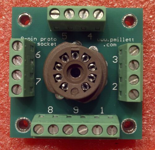
It looks like this:
As you can see, it has 18 screw terminals numbered 1 to 9. Each number on the board corresponds to one pin of the 9 pin tube, and the screw terminals allow you to connect two wires to each pin. Usually you only need one wire. A small flat blade screw driver is all that is needed. The board pictured here costs $24.00 and is US made. Look for
http://www.ebay.com/itm/9-pin-breadboard-prototype-tube-socket-for-DIY-experimenting-/151176364267?pt=Vintage_Electronics_R2&hash=item2332d040eb
-
-
-
There are other boards available for $7.00 to 15.00. For some reason availability varies, but the cheaper Chinese ones are well made.
This one sells for $15. The one below is Chinese and cost $7.00 but I do not see it on US Ebay right now. Available on European Ebay sites (for more money).
This model requires you to solder in little wires to connect the two little holes that are intended for resistors. Look for
1SET 9pin B9A tube test diy Experiment prototyping pcb for EL84 ECC83 12AX7 ECC8
Next you need two Vector adapters. The best price I have found is from Radiodaze ($5.00 each + shipping approximately $6.00):
http://www.radiodaze.com/vgm_search_result.aspx
Next you need stranded wire 22 AWG. The thickness of the wire is determined by what fits into the hole on the Vector tabs. I scavenged wires from a discarded PC power supply, but most anything will do, but do not use solid wire. At first I used very thin solid 30AWG wire wrap wire, but it had two disadvantages: It was too thin and broke off, and the insulation was also too thin, making it susceptible to electro-magnetic interference. Solid wire is less pliable and will make it difficult to close the Vector adapter.
You need something to strip the wires with, a wire stripper, cutting pliers, scissors or whatever. 9-10 " long pieces of wire is more than enough (need 9 pieces). The end for the breadboard screw terminal should be stripped approximately 2/16 "; the other end for the Vector about 3/8".
The Vectors are clever little devices, but can be very pesky. There is a threaded screw with a nut that goes through the adapter and holds it together. You need to take this screw out to work with the adapter. The nut on the bottom is tiny - make sure that your work surface does not make it disappear when it falls out, which it will. -Just thought of it; a little piece of tape will hold it in place so that you don't lose it.
AFTER TAKING OUT THE SCREW DO NOT SEPARATE THE ADAPTER INTO TWO PIECES!!! It will be extremely difficult to put it together. Just pull it apart a little. Use a little rubber band to prevent the pins from pulling out of the bottom piece.


As you can see, the tabs are numbered 1 to 7. Each tab is bent at a right angle, and the tab has a hole in it. Now carefully thread your wire through the appropriate hole. A small needle nose pliers will help. Twist together the end of the wire with the rest of the wire.

After the wiring is done, the adapter is pressed together, and the screw with a tiny lock washer on top is inserted from the top. The nut is held in place by a cutout. Tighten gently; overtightening can break the adapter. Believe it or not, this pressure fit of the wires gives better contact than soldering the wires. Make sure that no strands of wire can come into contact with an adjacent wire.

Insert the corresponding wires into the breadboard and tighten with a small flat blade screwdriver. It may be easier to do one wire at a time and do both ends before pressing together the adapter. After tightening all screws and connections, test all connections by pulling on them. Recheck that all the wires go to the proper places using the diagrams on pages 252, 253 and 275. There are three variations depending on which tube type you use.


You may want to put on something on the bottom of the bread board to keep the solder points touching the surface you are putting it on. There are four holes in the breadboard where you could put in screws with nuts to lift it off the surface. I used a little piece of self stick foam i found, maybe from a piece of door insulation.

The last two pictures show the screw and nut.


Here is wiring diagram for a 12AX7 tube:
12AX7
9-pin socket left LD socket right LD socket
1 plate triode 1 5
2 grid triode 1 1
3 cathode triode 1 2
4 heater 3
5 heater 3
6 plate triode 2 5
7 grid triode 2 1
8 cathode triode 2 2
9 4
Just look for screw terminal 1 on the breadboard and connect the wire to the left Vector #5 etc etc. Once you are finished it does not matter which side of the Little Dot amp you plug in the adapters. Right and left are only for the purposes of routing the the correct wires.
Here is the diagram for 6DJ8 tubes:
9 Pin socket Left LD socket Right LD socket
1 plate triode 1 5
2 grid triode 1 1
3 cathode triode 1 2
4 heater
3
5 heater
4
6 plate triode 2 5
7 grid triode 2 1
8 cathode triode 2
2
9 Shield tied to pin 8 at the socket (Use short wire to connect terminals 8&9 together on the breadboard only.)
As you can see, the changes from 12AX7 to 6DJ8 only involve one of the adapters. If you want to change the wiring, only do it at the breadboard terminals; leave the adapter connections where they are.
With the 12AX7 setup you can buy a plug in adapter to play octal 6SL7 and 6SN7 tubes. The 6SN7 draws more current than the Little Dot can handle, so you will need an external power adapter such as an old laptop adapter and a voltage regulator.
I have tried to be very thorough in showing how to build an adapter and how easy it really is when you have the right parts. This is a first draft, and there may be errors and omissions. Please submit your comments and suggestions on how to improve this post.
Many thanks to AFB for coming up with the original flying tube adapter and to Gibosi for posting the diagrams and overall guidance, and to all others who have contributed and helped to enhance the Little Dot listening experience.
Happy tube rolling!