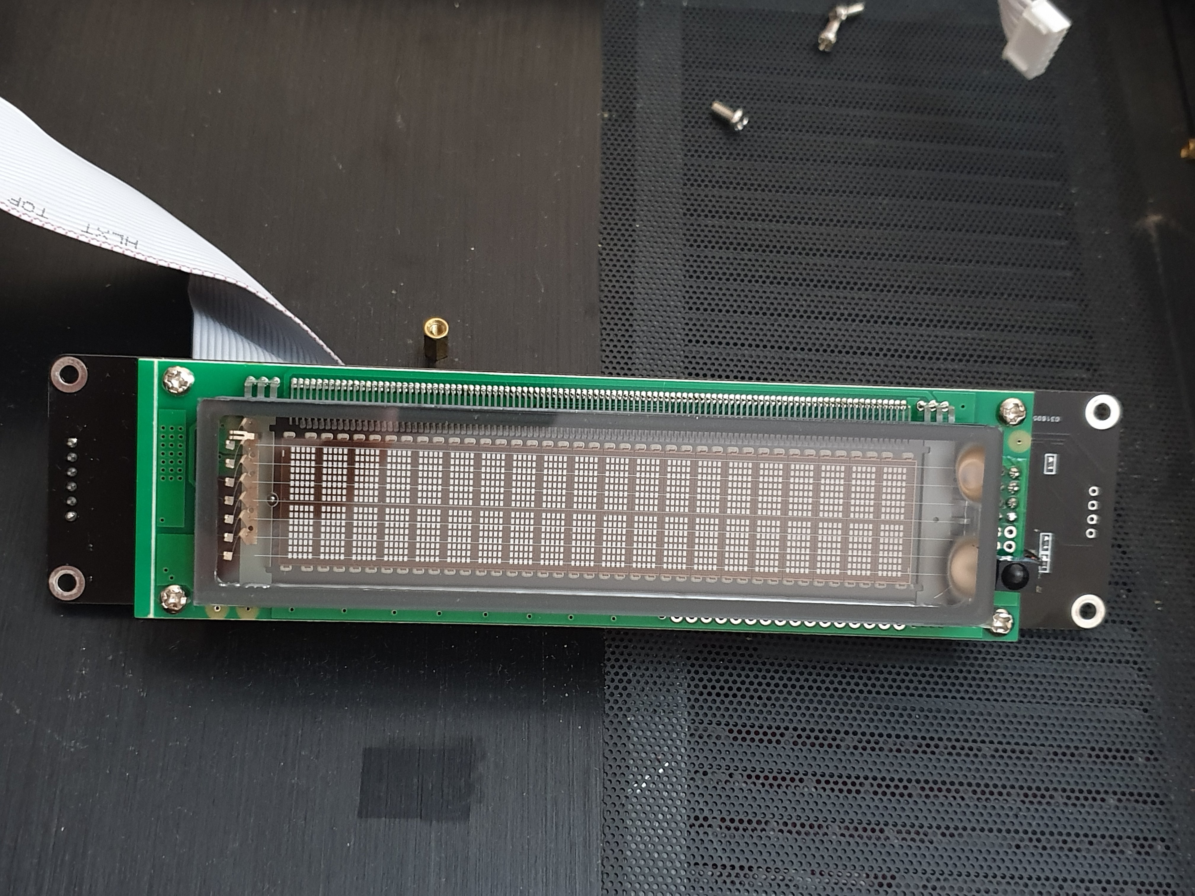
My bad ... the LKS display uses a parallel interface.
To use Ian Canada's controller board, this is what he said:
Works with external ESS DAC
It's also possible to make this ESS controller working as a dedicated controller of
an external ESS DAC even without a Raspberry Pi.
To do so, you will need:
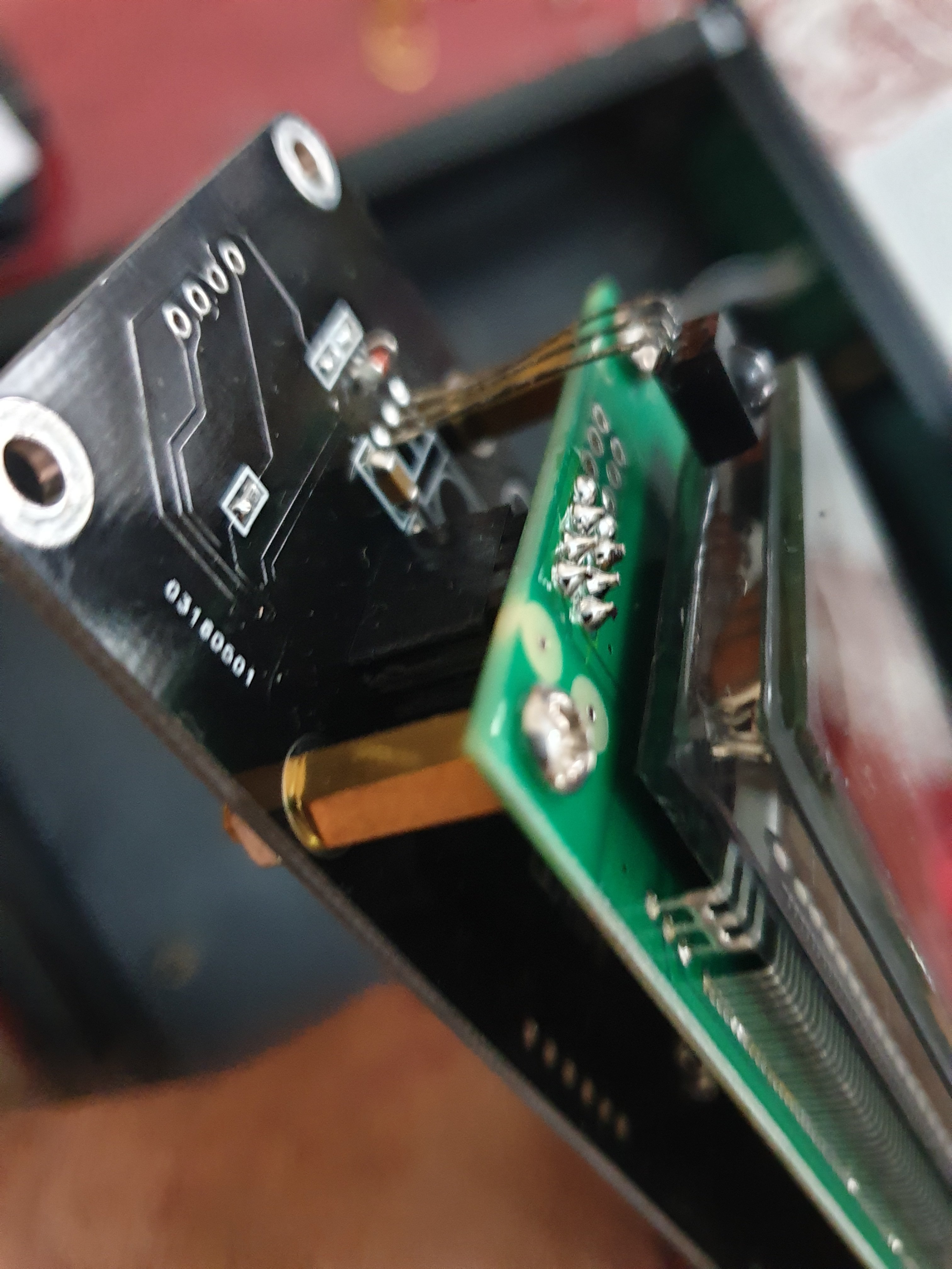
1. Solder the 10 wires of the cable to the footprint of J3.
2. Connect the wires of the cable to the corresponding signal pins of the DAC.
3. Remove any possible local controller that connected to the I2C bus of the ESS DAC.
Also make sure I2S bus has pull-up resistors for both signals.
https://github.com/iancanada/DocumentDownload/tree/master/ESScontroller
Point #3 makes it infeasible.