Power Equation:
Power = Voltage * Current
P = V * I (1)
Units: Watts = Volts * Amperes
Ohm’s Law:
Voltage = Current * Resistance
V = I * R
Re-arranged: I = V / R (2)
Units: Amperes = Volts / Ohms
Re-arranging Equation (1) to include Equation (2):
Power = Voltage * (Voltage / Resistance)
P = V * (V / R)
P = (V^2) / R (3)
Units: Watts = Volts^2 / Ohms
Voltage_RMS = peak-to-peak Voltage * log(2) (4)
Units: Volts = Volts
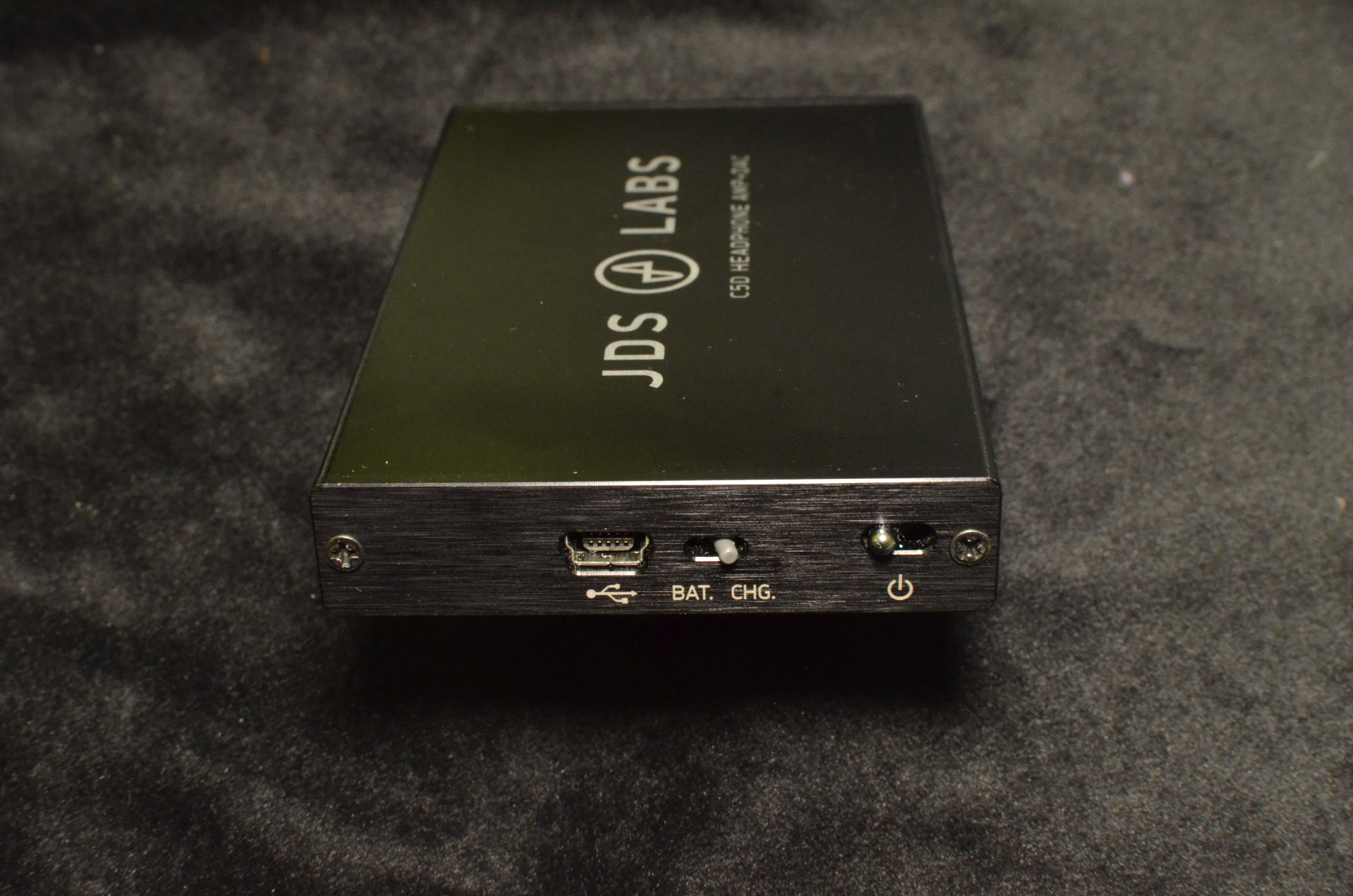
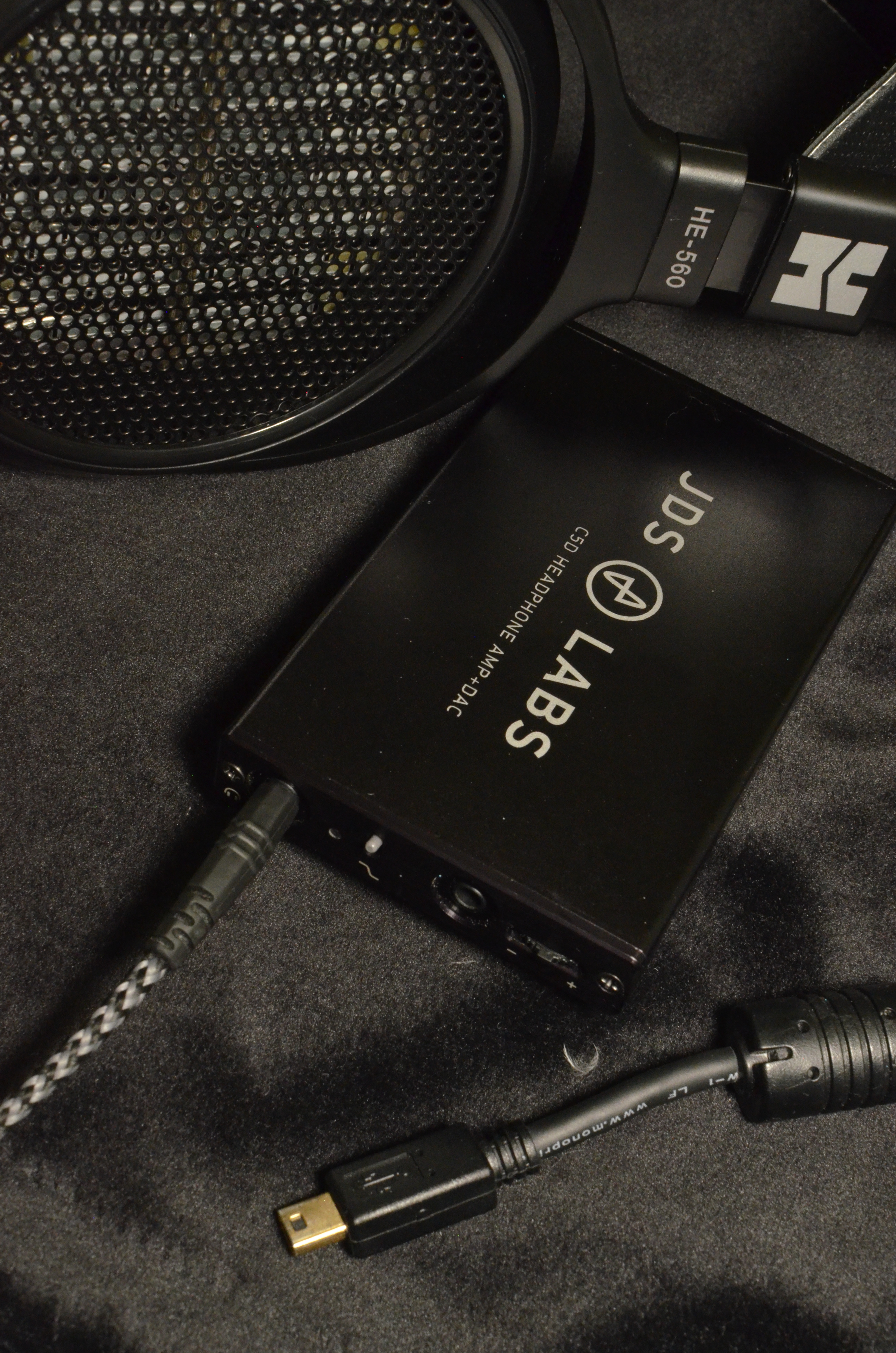
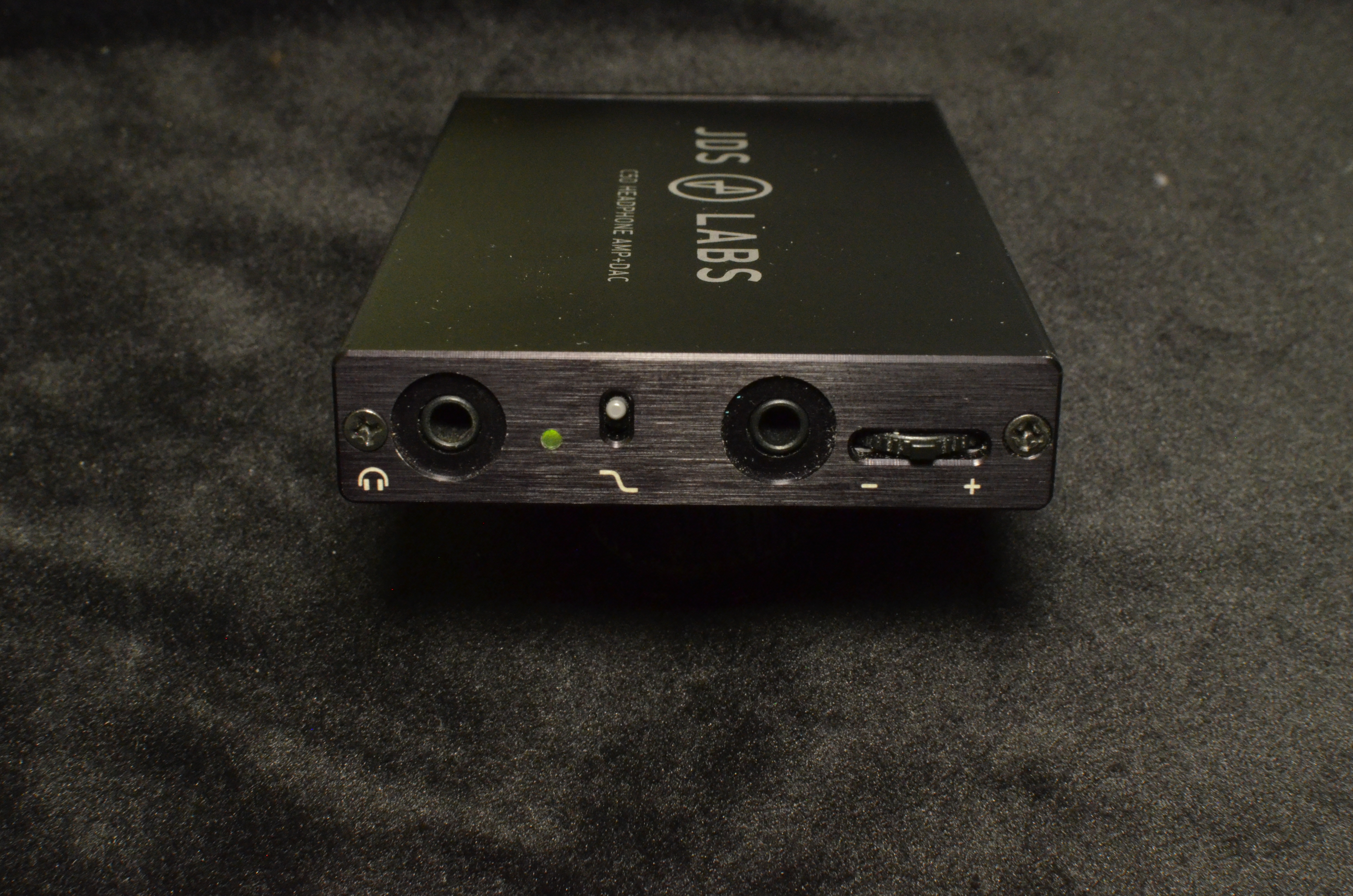
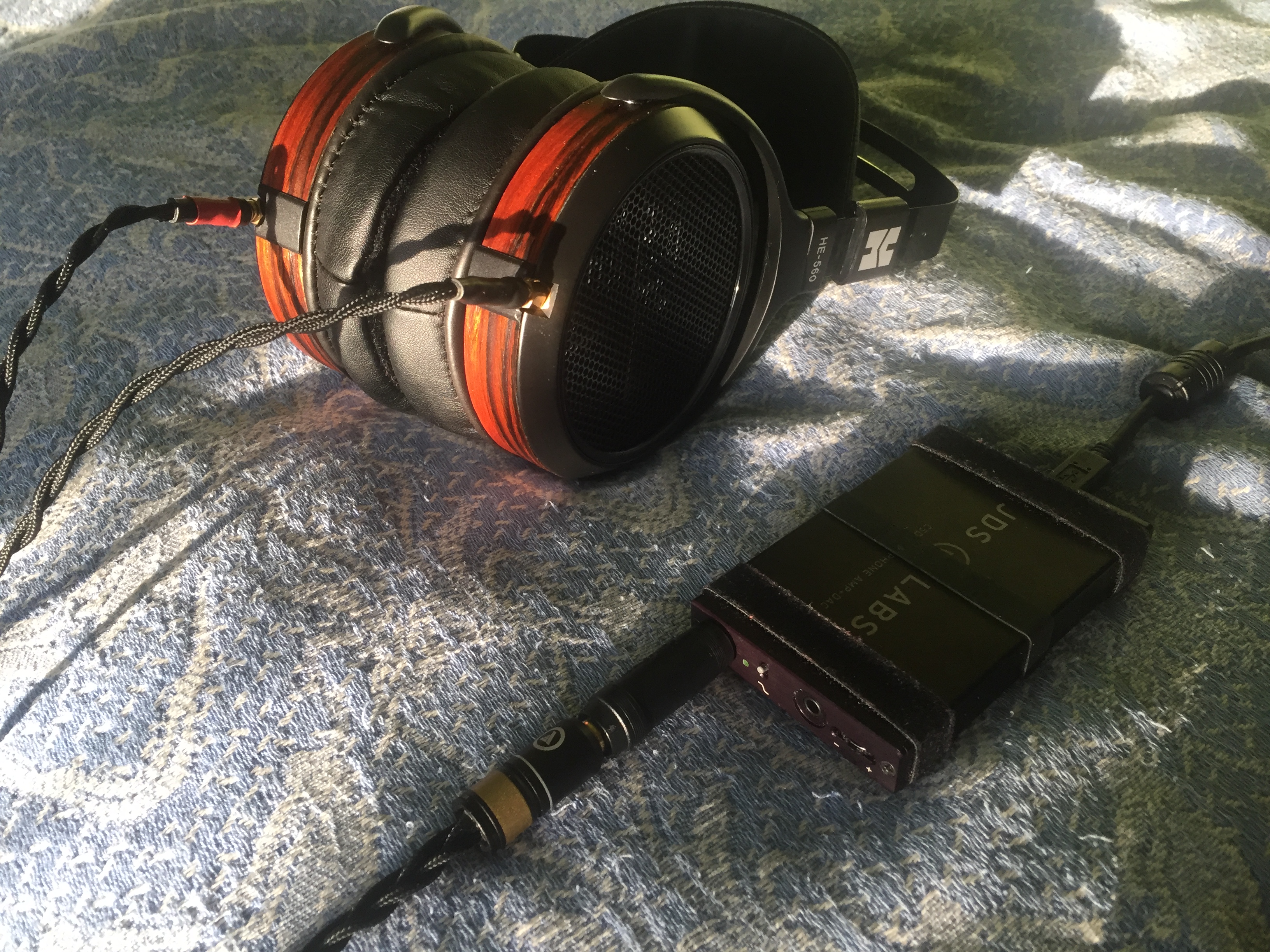
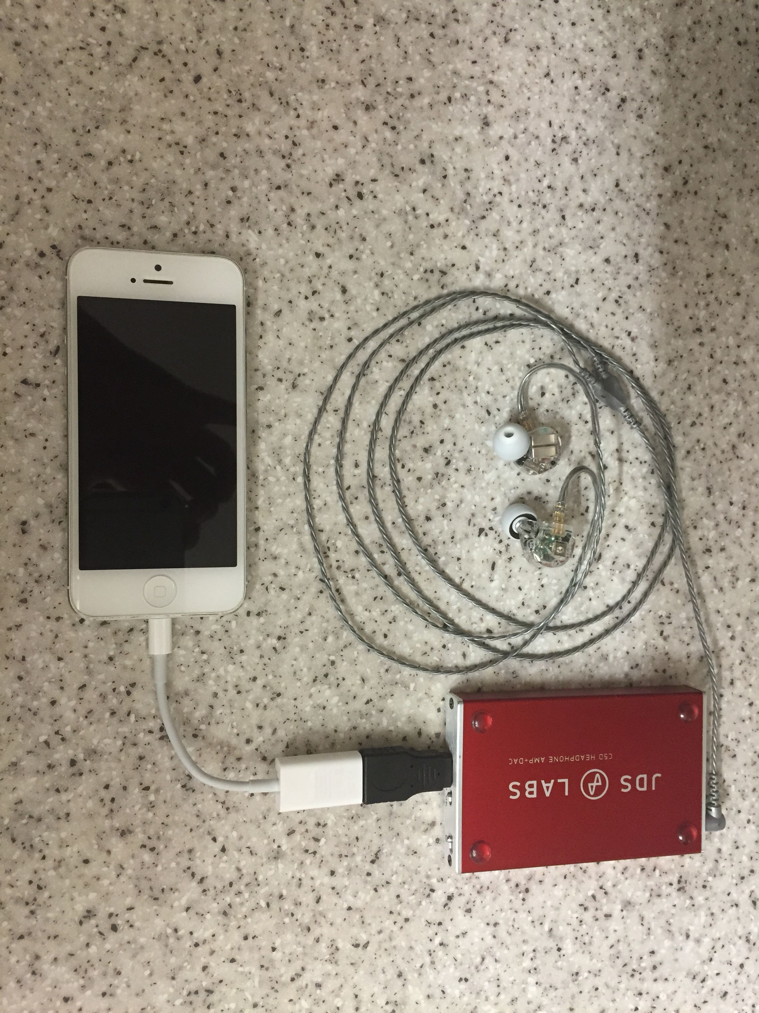
From JDS Lab’s official C5 blog post:
3.337 VRMS @ 150 Ω
4.146 VRMS @ 600 Ω
14.0 Vpp (peak-to-peak voltage)
Therefore, from Equation (4):
Voltage_RMS = 14.0 Volts peak-to-peak * log(2) = 4.214 Volts [this is basically the maximum voltage the C5 can output without clipping the source’s signal]
RMS (root mean square) is basically an average value
From Equation (3):
P = ((3.337 Volts_RMS)^2) / 150 Ω = 0.07424 Watts, or
74.24 milliWatts @ 150 Ω
P = ((4.146 Volts_RMS)^2) / 600 Ω = 0.02865 Watts, or
28.65 milliWatts @ 600 Ω
Extrapolating values assuming the behavior is linear (straight-line approximation):
Slope = Rise / Run
Slope = ΔPower / ΔImpedance
Slope = (P2 - P1) / (600 Ω - 150 Ω) = (28.65 milliWatts - 74.24 milliWatts) / (600 Ω - 150 Ω)
Slope = -0.1013 milliWatts/Ω
Using the slope value, the power supplied to headphones of other impedances can be extrapolated (again, assuming linear behavior):
Slope = Slope
-0.1013 milliWatts/Ω = (74.24 milliWatts - X) / (150 Ω - 32 Ω)
X = 0.1013 milliWatts/Ω * (150 Ω - 32 Ω) + 74.24 milliWatts =
86.19 milliWatts @ 32 Ω
-0.1013 milliWatts/Ω = (74.24 milliWatts - X) / (150 Ω - 16 Ω)
X = 0.1013 milliWatts/Ω * (150 Ω - 16 Ω) + 74.24 milliWatts =
87.81 milliWatts @ 16 Ω
-0.1013 milliWatts/Ω = (74.24 milliWatts - X) / (150 Ω - 300 Ω)
X = 0.1013 milliWatts/Ω * (150 Ω - 300 Ω) + 74.24 milliWatts =
59.05 milliWatts @ 300 Ω
-0.1013 milliWatts/Ω = (74.24 milliWatts - X) / (150 Ω - 50 Ω)
X = 0.1013 milliWatts/Ω * (150 Ω - 50 Ω) + 74.24 milliWatts =
84.37 milliWatts @ 50 Ω
-0.1013 milliWatts/Ω = (74.24 milliWatts - X) / (150 Ω - 62 Ω)
X = 0.1013 milliWatts/Ω * (150 Ω - 62 Ω) + 74.24 milliWatts =
83.15 milliWatts @ 62 Ω
A linear plot of all of these values:

If any of my calculations are wrong, please let me know.
")