Jambo DAC
Jun 19, 2010 at 2:13 AM Post #197 of 221
I was looking on audiologica about the TREAD power supplies and i noticed the new version of the STEPS called the YJPS, has anyone tried this? i was wondering because i hopefully will be trying this for my first build and i want to start on the power supply before i get the kit.
 
Jun 19, 2010 at 4:53 AM Post #198 of 221
The yjps is a very nice single rail power supply with very low output impedance and good ripple specs, but I think you need a few different supply voltages with this dac.. Probably the AVDD and DVDD for the wolfson chip, and +/- supply for the output stage.  
 
4x yjps would cost more than the DAC itself and would take up a lot of physical space.  I think twisted pear's dual and bipolar psu offerings would make the most sense, while amb's sigma25 and tangent's treads would also work well.
 
 
Jun 19, 2010 at 9:50 AM Post #199 of 221
o alright, i did look at TREADs and they seem simple enough, now i have no idea whats what when it comes to like power (this will be my first official audio DIY) so could you explain to me how these work, i do keep seeing you need 4 TREADs is that like one for 3.3V, 5V and then +/-12V each? if so is there a way on the chip to change the output or how does it all work?.
 
or if i were to do the sigma 25, do you just need the one and its can handle all of the different power needs?
 
also last question, can you hook up all 4 treads like in one box so it only has one power cable or something like that?  (probably a dumb noob question haha)
 
EDIT: i thought i read earlier in the thread that the DAC only supports 44.1kHz and i assume only up to 16bit playback is this true?
 
Jun 22, 2010 at 5:51 AM Post #200 of 221


Quote:
o alright, i did look at TREADs and they seem simple enough, now i have no idea whats what when it comes to like power (this will be my first official audio DIY) so could you explain to me how these work, i do keep seeing you need 4 TREADs is that like one for 3.3V, 5V and then +/-12V each? if so is there a way on the chip to change the output or how does it all work?.
 
or if i were to do the sigma 25, do you just need the one and its can handle all of the different power needs?
 
also last question, can you hook up all 4 treads like in one box so it only has one power cable or something like that?  (probably a dumb noob question haha)
 
EDIT: i thought i read earlier in the thread that the DAC only supports 44.1kHz and i assume only up to 16bit playback is this true?


Yes, you would need 4 treads.  A TREAD uses the lm317 by default which is an adjustable regulator.. you should choose the components based on the approximate voltage you want, and you can fine-tune the voltage through the trimpot that is on-board.  One board would supply the 3.3v, one would supply the 5v, and two boards would be used to provide the +/-12v.
 
The sigma 25's work the same way.  The main difference is that it uses the lm78** series of regulators instead of the lm317.  The lm78** is not a adjustable regulator, but is a series of regulators that have a fixed output voltage.  
 
tangentsoft and amb's website both have diagrams to show how to wire the transformers to make a bipolar supply
 
yes, you could put all 4 treads in one box and use a single power cable, as long as the connector has enough contacts.
 
Jun 22, 2010 at 2:23 PM Post #201 of 221
well since from what ive read the Jambo only supports 44.1kHz i decided to go with the AMB y2 (with the y1 full++)
 
thanks for the info i might build this later just for fun though, so good to know
 
Jun 25, 2010 at 1:58 PM Post #203 of 221
The Jambo DAC and AMBs gamma 2 use the same wolfson dac chip.  If the gamma 2 supports a higher rate then the Jambo DAC should also.  I have built two Jambo DACs and think they are fantastic but it is a very complex build so maybe not the best candidate for a first DIY project. 
 
Jan 10, 2011 at 12:12 PM Post #207 of 221
Evening folks, finally got some decent time off work and I've done some more work on this project. I've finally got round to adding an LCD screen!
 
You'll notice that I have used one of my old prototyping boards rather than the smart black ones that are available for those who order a kit.
 
Here's the startup screen, shown each time the power is cycled:


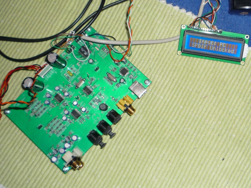
And then the current input source is displayed along with the SPDIF interface status (read from the WM8805):


By changing just a few lines in the C source code you can name the inputs as you like.
 
When the SPDIF interface is locked I want it to show the sample rate. However, so far as I can ascertain the WM8805 does not allow this to be done precisely, it seems like it can only indicate the following:
 
  1. 32 kHz
  2. 48 or 44.1kHz
  3. 96 or 88.2kHz
  4. 192kHz
 
I don't think I really want to put '48 or 44.1 kHz' on the display!? I may assume that 48kHz and 88.2kHz are never used, we'll see...
 
I had to sacrifice some switches and the LEDs to do this. It now only has one source selection switch which cycles through the available inputs, rather than having a switch for each input. Aside from the LCD screen itself (with HD44780 driver) and wiring, no hardware modifications are needed, except that the 5V supply for the LCD should probably be isolated from the analogue 5V supply.
 
The LCD screen in the picture I picked up on ebay for 3 GBP delivered, I'm sure it's possible to get a much nicer display.
 
The hex will be available to anyone who wants it. If ordering a kit, specify which version of the hex you want on your micro, of course the previous version is still available. My recommendation would probably be to go with the 'basic' version first and get everything working, then make your own programming cable if and when you go down the LCD route.
 
I'll release an updated schematic when I get time to show how the LCD is wired up.
 
Questions welcome.
 
Cheers
 
Jamie
 
Jan 10, 2011 at 2:01 PM Post #208 of 221

 
Quote:
 
When the SPDIF interface is locked I want it to show the sample rate. However, so far as I can ascertain the WM8805 does not allow this to be done precisely, it seems like it can only indicate the following:
 
  1. 32 kHz
  2. 48 or 44.1kHz
  3. 96 or 88.2kHz
  4. 192kHz
 
I don't think I really want to put '48 or 44.1 kHz' on the display!? I may assume that 48kHz and 88.2kHz are never used, we'll see...


That's great, Jamie.  Hmm, I might have to recase for this.  You do want to put 44.1.  I also think some people like to upsample to 88.2KHz.  You seem to come across this quite a bit in the Computer Audio sub-forum, as 88.2 is a 2x upsample instead of fractional.
 
Jan 10, 2011 at 4:21 PM Post #209 of 221
I've just realised that DAT is 48 kHz so really I need to be able to determine that one also.
 
What were wolfson thinking!!
 
Turns out R16 will let me get the indicated sample rate from the SPDIF stream (to be honest, I didn't realise that that was included in the stream), rather than the recovered frequency from the WM8805 which I really wanted to get. I guess it should be accurate enough. It's a 4 bit word, but the Wolfson datasheet says to refer to the SPDIF spec for how to decode it. Argh. It is not free.
 
I found this much from the helpful people at minidisc.org:
Code:
 27 26 25 24 Sample frequency Fs ------------------------------------------- 0 0 0 0 44.1kHz 0 0 1 0 48kHz 0 0 1 1 32kHz or sample rate converter - - - - Reserved
 
Odd that only 3 rates seem to be defined when the bits allocated can indicate 15 different rates...
 
Anyway, if I read these two registers then hopefully the only uncertainty would be between 96kHz and 88.2kHz...
 
Jamie
 
Jan 19, 2011 at 2:10 AM Post #210 of 221
Jamie,
 
This is great, I would certainly try out your new  code which supports LCD. Also is the LCD interface serial or parallel. I picked up a parallel LCD locally here for $4 and was planning to wire it up with the DAC.
 
Regards
free2dev
 

Users who are viewing this thread

Back
Top