Introduction to DIY Questions and Cmoy Contruction

Feb 6, 2009 at 8:43 AM Post #16 of 58
I wouldn't recommend 60/40 personally. It's not eutectic, meaning that it does not make an instant transition from solid to liquid - it goes pasty in between, which can let wires move and can cause a cold solder joint (a bad electrical connection). Sure, done properly you can avoid this, but why bother? 63/37 or 62/6/2 is easily found at any Radioshack or similar electronics store.

As far as background, I'm an Electrical Engineering major graduating in 1-2 years (with a little luck), but they don't teach how to physically make things in college. I can understand the circuit diagrams and what all those components do, but it's really not necessary for DIY audio - someone has already designed the circuits, all you have to do is solder them together.
 
Feb 6, 2009 at 9:48 AM Post #17 of 58
We are in Australia and 60/40 is the best we can get at a reasonable price all you have to do is not move the joint untill the solder cools about 1/2 second
 
Feb 6, 2009 at 3:10 PM Post #18 of 58
haha 1/2 second? I think I'll be able to hold everything still for that long.

Juaquin, I actually looked for 63/37 in Jaycar but they didn't stock it. Thanks for the advice though
 
Feb 6, 2009 at 4:05 PM Post #19 of 58
I made couple diy amps / dacs and cant read a schematic or learned electronics.

Heres how one noobb goes about it.

0. Read threads regarding amp build here & headwize. Take notes.
1. pictures, grab lots of pictures of finished boards.
2. get a BOM, when ordering make sure to type in the part number which correspond the board to the part. (mouser & digikey has this feature)
3. Double check and recheck the ordered parts and the number matches.
4. Find out which parts are polar and needs to be placed in a specific direction.
5. Then its just almost like color by numbers, plugin in the parts on to the board. The parts will come in its own little bags with the board number printed on them.
6. Make sure solder connections are good and test them with a meter.
7. Double checking resistors are correct even though they are labeled right.
8. Read through the wiring instructions, I take these wiring layouts and put them on photoshop to color coordinate them.
9. Gain basic knowledge of wiring pots, rca, i/o jacks, etc..
10. check continuity with meter, plugin power, measure point on the board with multimeter as instructed, check dc offset,
11. Listen to magic!
ksc75smile.gif
 
Feb 7, 2009 at 8:46 AM Post #20 of 58
Hey keyid, that seems like a great step by step guide for beginners to go about a project, I'll definitely refer to it
smily_headphones1.gif


Ok so as for now, I don't have a multimeter or wire stripper yet so all I did was install the jumpers. Thing is, I've read around and people have talked about solder bridges, which are.. bad? What are solder bridges anyway? Does that mean on the board, the solder on each hole can't touch other solder on the hole next to it? I really don't know much about soldering at all so if anyone could help me out it would be great.

I would post pictures up of what I've done so far but I can't upload the photos until I've found the cable..
 
Feb 7, 2009 at 9:47 AM Post #21 of 58
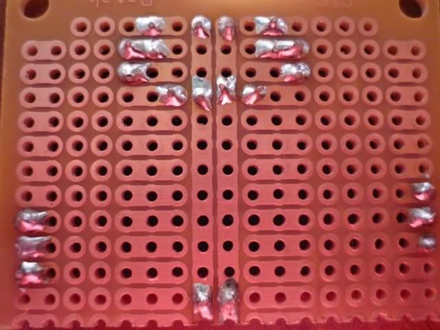
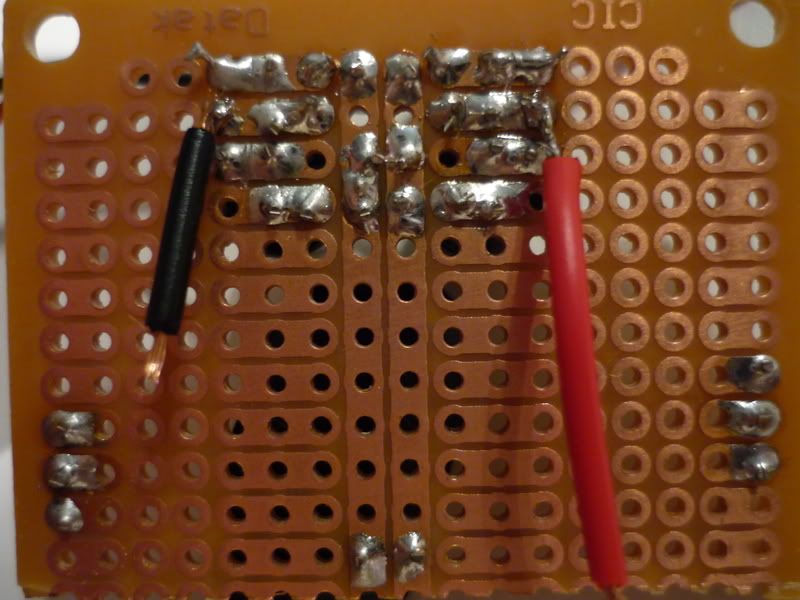
Yep, that is what a solder bridge is, solder touching on both holes, or both legs on a microchip(quite common on small chip legs).

In my experience, the only cause of my projects not to work the first time I switch them on was either a solder bridge or a cold solder joint. So check your work with a magnifying glass for solder bridges, and reflow the solder joints if your project doesn't work the first time.

Also, buy a help hand, the thing that is holding up my mini3, don't start a project without one!
dsc0580yj4.jpg


If you haven't soldered before, watched the soldering videos on tangent, Tangent Tutorials , and perhaps buy a cheap circuit board and some parts, the practice on that. The tangent videos were great, definitely was a solid guideline for me when I tackled the mini3, then onto surface mount soldering on the alien dac.

I recently finished a mini3 and an alien dac as my first diy projects. It really wasn't hard, what really helped me were the tangentsoft.com soldering tutorials, and finished pictures of other people's builds, so I can check against their working boards with my own. After you are finished and if it doesn't work, people on here will help you sort through the problem.

dsc0589rz5.jpg

These are the tools I used to build the mini3 and the Alien dac, without any one of them I couldn't have finished the projects.

Multimeter- a must for trouble shooting, I would measure the voltages or ohms for set points on the board to check if I get the correct measurement suggested
Solder
Safety glasses- I try to wear these as much as I can, hot stuff with splash around whenever I tin my soldering iron
Desoldering braid(light blue thing with cuppoer braid)- to suck up solder when you need to take a component out, or clean up excess solder
Wire cutters- to cut wires and excess pin from resistors, caps
tweezers- hand small parts and to avoid heat from soldering iron
Helping hands with magnifiying glass- couldn't have done the projects without this
soldering iron with stand and sponge- set your soldering iron in the stand for safety, and always clean your soldering tip with the sponge, pretty much after every solder joint
Soldering paste or flux(the blue tub)- to make a better soldering joint, but I didn't really use it as my solder already has flux in it

Oh and a multimeter is absolutely necessary, you should be able to get a cheap one for around $10 USD. Mine was like $8USD bought here in Hong Kong.

Keyid pretty much hit the spot with the steps.
 
Feb 8, 2009 at 6:54 PM Post #22 of 58
Hey everybody,

I am also getting ready for some diy stuff. just got the hakko 936 soldering station. my question is, which size iron should I start with. I got this as a gift, and it came with the small iron. they have small, medium(standard) and large. I thought I asked for the medium. any recommendations? I can easily exchange it since I just got it.
 
Feb 8, 2009 at 6:55 PM Post #23 of 58
Hey everybody,

I am also getting ready for some diy stuff. just got the hakko 936 soldering station. my question is, which size iron should I start with. I got this as a gift, and it came with the small iron. they have small, medium(standard) and large. I thought I asked for the medium. any recommendations? I can easily exchange it since I just got it.
 
Feb 8, 2009 at 7:04 PM Post #24 of 58
I think what you can look for is the number on the iron itself. My iron has "Hakko 907" on it, and this is the 936-12 medium model. If it is the small version, 936-11, I believe it may have "900S" on it.

Look at the bottom of the page here for a chart. I can't find any pics.
 
Feb 8, 2009 at 7:35 PM Post #25 of 58
Quote:

Originally Posted by Fred_fred2004 /img/forum/go_quote.gif
We are in Australia and 60/40 is the best we can get at a reasonable price all you have to do is not move the joint untill the solder cools about 1/2 second


You can get some 63/37 on DX for a few bucks: DealExtreme: $4.15 0.3mm Solder Wire. It's pretty fine but I'm sure they have others.
 
Feb 9, 2009 at 3:41 PM Post #26 of 58
Hey Chiefroastbeef, your tool collection looks VERY similar to what I have, awesome helping hands!

Ok so I finally got some pictures uploaded.

P1030619.jpg


Oh dear, terrible right? I was so annoyed i gave it another go.

P1030644.jpg


What do you guys think? Good enough?
 
Feb 9, 2009 at 3:57 PM Post #27 of 58
Looks good to me, but then what do I know?
tongue.gif


You can probably kung fu with a little less solder.
 
Feb 9, 2009 at 11:02 PM Post #28 of 58
Looks like it should work to me. A few of the joints (especially those on the bottom) look cold, so for the best audio signal you should reflow them with some flux, but as it is now you should at least get a pretty good signal.

I'll echo the "you could use a little less solder" statement, but it's not a huge deal unless it starts to bridge.
 
Feb 11, 2009 at 3:38 PM Post #29 of 58
So i went to work on the power supply of my cmoy and i think i may have buggered it up :/

I tried to test it with a multimeter by measuring from the jumpers right at the bottom of the board which are meant to be ground with the ends of the loose hook-up wire. Is this correct? Because i got no reading at all..Is this because I'm not using the multimeter correctly? Or could it be due to solder bridges? The LED lit up though

Here are some pics of my crappy soldering:

P1030782.jpg


P1030784.jpg


Whats wrong?
 
Feb 11, 2009 at 4:05 PM Post #30 of 58
Your soldering isn't bad for a beginner. Using some flux will definitely clean up your joints though.

Your meter needs to be on the VDC setting. I'm not sure what your meter is, on all of mine, DC is a 'V' with a straight line over the 'V'. If your probes aren't captive (attached to your meter), then make sure you have the common probe (which is usually black) in the 'COM' socket. Then, make sure you have the 'V' probe (which is usually red) in the 'V' socket, or + socket.

Tangents website has a great video on how to use a DMM:
How to Use a Multimeter

I can't see anything catastrophically wrong with your board, and obviously the LED works. The pictures come come out a little dark on my LCD. Hopefully someone with a better display can see a problem I possibly can't.
 

Users who are viewing this thread

Back
Top