How is Khozmo Stepped Attenuators?
Sep 29, 2009 at 3:11 PM Post #123 of 440
Quote:

Originally Posted by n_maher /img/forum/go_quote.gif
Correct, and my emails have not been responded to for over 2 weeks. Sad.


More than sad. Didn't you say you'd ordered 20 of them? And I assume you paid for them?

I don't get it. I'm pretty sure those images aren't just computer generated renderings. Somebody went through some trouble to make those parts.

k
 
Sep 30, 2009 at 8:38 PM Post #124 of 440
I emailed him and he is still taking orders, wich I find a little strange because nobody received the attenuators yet and he isn't responding to n_maher.
Also, the balanced attenuators look very different you than would expect from the pictures.

Responce to my email:

Thanks for interesting on my products.
The balanced (shunt and ladder) version is offered only with military Vishay/Dale RN55 resistors (see attached pics).

I accept paypal.

Best regards
Arek Kallas
High Quality Audio & Industrial Attenuators


With the following pictures:

dale_shunt_4.gif


dale_ladd_8.gif


dale1.jpg
 
Sep 30, 2009 at 9:23 PM Post #127 of 440
Hmm... well, if it's simply RN55 axial resistors, that's not too different from more "common" types. SMC 0.1% thin film resistors generally have lower noise and better tolerance, plus the lack of lead inductance.

Very bad that they're ignoring Nate, strongly recommend not ordering anything from them until they clear things up.
 
Sep 30, 2009 at 10:55 PM Post #128 of 440
Quote:

Originally Posted by les_garten /img/forum/go_quote.gif
Something Fishy in Denmark, errr Poland in this case....


Yeah.

He's yet to deliver what he was originally offering, and now he's got something completely different that he's selling?

Oh yeah, and he's accepting PayPal again?

k
 
Sep 30, 2009 at 11:44 PM Post #129 of 440
Quote:

Originally Posted by Koyaan I. Sqatsi /img/forum/go_quote.gif
I don't get it. I'm pretty sure those images aren't just computer generated renderings. Somebody went through some trouble to make those parts.

k


I may be wrong, but if this was a real picture, why would every resistor be the same? If there was only two resistors in the path, wouldn't some of these have to be different?

index_r9_c1.jpg
 
Oct 1, 2009 at 12:12 AM Post #130 of 440
^ I was thinking the same thing (especially since they're 100k), although I don't really know anything about these.

Anyways, whether or not these products actually exist, this is clearly a very shady "business".
 
Oct 1, 2009 at 12:41 AM Post #132 of 440
maybe, but if this attenuator (from gold point website) had all 100k ohm resistors, then its input impedance would be 100k ohm x 24 steps = 2.4M ohm
...doesn't seem right

sch_mv.gif


EDIT also looking at this schematic, the image of Khozmo makes even less sense since on the Khozmo all the resistors are connected together on one end.

EDIT 2 ah, that's a series type. Haha oops, disregard the above
redface.gif
 
Oct 1, 2009 at 1:08 AM Post #133 of 440
Quote:

Originally Posted by FallenAngel /img/forum/go_quote.gif
If it's a ladder type attenuator wouldn't the resistors to ground all be same?


No.

k
 
Oct 1, 2009 at 1:11 AM Post #134 of 440
Quote:

Originally Posted by cobaltmute /img/forum/go_quote.gif
I may be wrong, but if this was a real picture, why would every resistor be the same? If there was only two resistors in the path, wouldn't some of these have to be different?


Yes, they would.

I've no explanation for why they're not.

k
 
Oct 1, 2009 at 1:27 AM Post #135 of 440
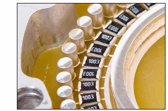
It makes perfect sense if you're looking at the ground leg deck of the attenuator at the full-attenuation end.

A ladder attenuator with 2dB steps starting at -60dB would have at least 10 resistors on the signal leg side that are equal to the nominal attenuator impedance. The photo has 10 visible resistor markings.

Example: I have one of the old 23-position Elna ladder attenuator switches. If I made a 100K attenuator, the signal leg resistor for -60dB, -55dB, -50dB, -45dB, and -40dB (positions 1-5, less control at the low end) would all be 100K resistors. The ground legs would be, respectively, 100 ohm, 180 ohm, 340 ohm, 560 ohm, and 1000 ohm. Yes, ideally the -40dB step would actually be 1000 ohm / 99K, but there is no 99K resistor in typical product lines. The closest value is still 100K. Next closest is 97.6K.

Values are generally the same regardless of order. You would expect 1K/100K at the -40dB step, and a 97.6K signal leg resistor for the next value, or the one after that. If using a resistor series with fewer standard values, you would get a few more steps with 100K signal leg resistors.
 

Users who are viewing this thread

Back
Top