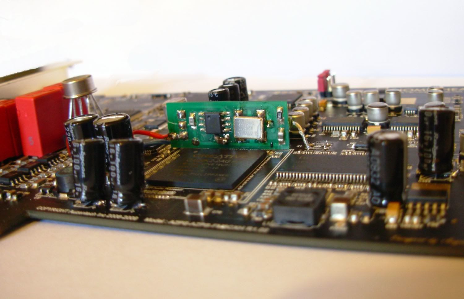
As you can see from following picture, dac doesn't get instantly damaged if it is soldered on. It is really difficult to get good solder joints on those small legs, as my soldering iron tip is 1.2 mm and those legs are 0.2 mm wide
Cable is shielded and grounded
(that residue has been cleaned away)
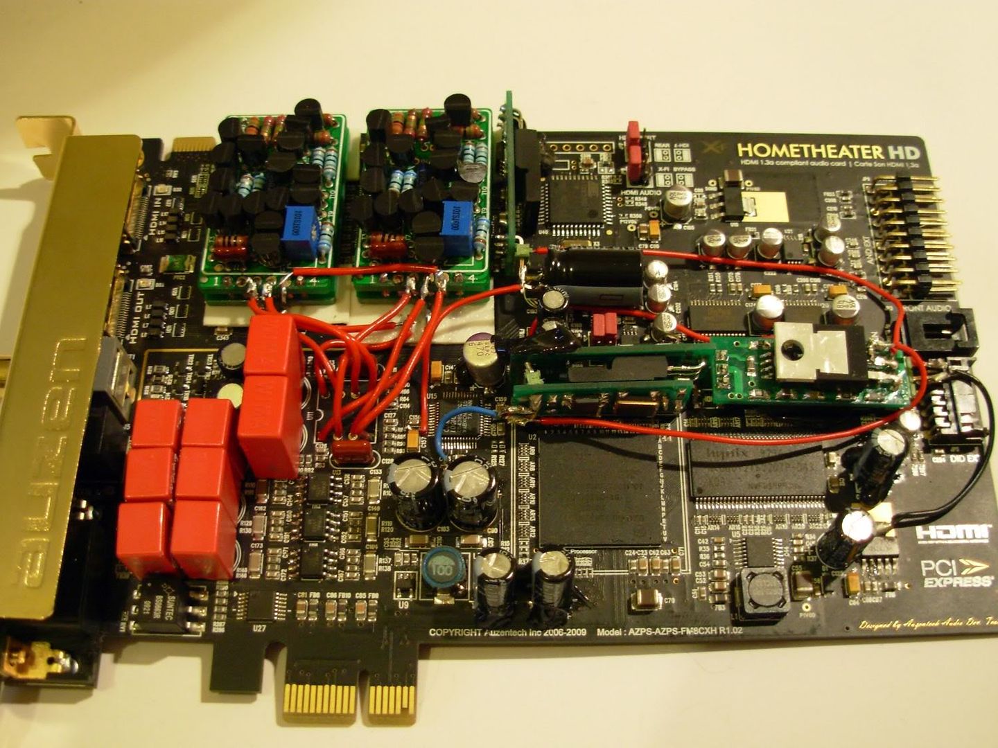
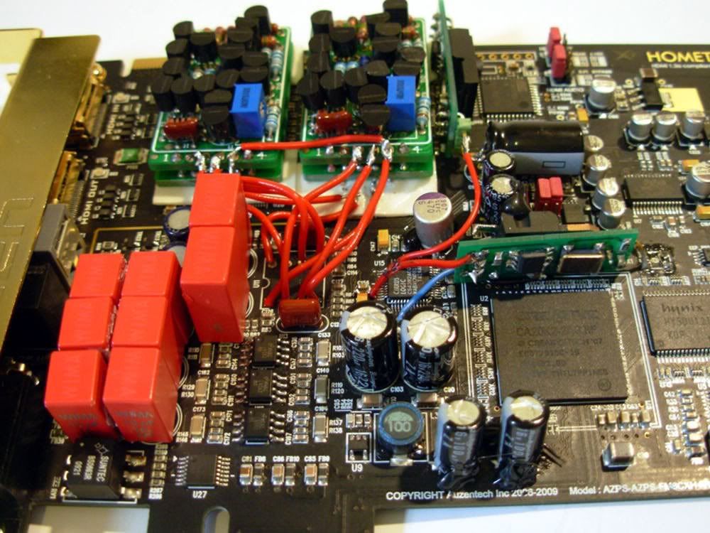
I have removed most of the not important stuff from the signal path. I have created my own dip to soic adapter. Only 2 Jamicons left on the card, those shouldn't affect performance. I am trying to balance the capacitor values.
Mic-in op amp changed to OPA2211
Currently AD8620 installed on the adapter
See:
http://i40.tinypic.com/2ui8ah1.jpg
Test results, current configuration is on the left
http://i44.tinypic.com/2vnp76b.jpg
I am a bit disappointed now to the THD value. 0.0026% and on the default card it is 0.0017%. I cannot resolder my adapters connections anymore because I epoxied it to the card. But they are shiny!
THD might be limited by something else. Like socketed capacitors.
The sound quality overall is SUPER. The details of the sound signature depends very much on the op amp now. The CS4382 is pretty very neutral sounding DAC. I almost mixed up the DAC for bright sounding, but then I remembered that I have AD8620 on there so that is the reason for bright sound.