Hello, Looks very good. I wanna to know how the faceplate firmly attached to the shell ? Can you tell more about this. Thanks !The face plate can be replaced. I made different designs of faceplates using various techniques. You can exchange it depending on the mood of the day.
You are using an out of date browser. It may not display this or other websites correctly.
You should upgrade or use an alternative browser.
You should upgrade or use an alternative browser.
Home-Made IEMs
- Thread starter Bilavideo
- Start date
All IEMs have a common shape for the faceplate mounting area.Hello, Looks very good. I wanna to know how the faceplate firmly attached to the shell ? Can you tell more about this. Thanks !
The face plate has a convex part that fits into the IEM.
Use a kneaded eraser when fitting to make it more difficult to remove. The kneaded eraser is a little sticky (but easy to peel off) so you can put it on and take it off again and again.
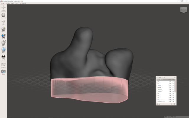
Synthesize common shapes.
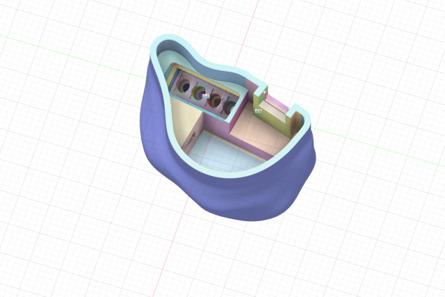
The part where the face plate fits is all the same shape.
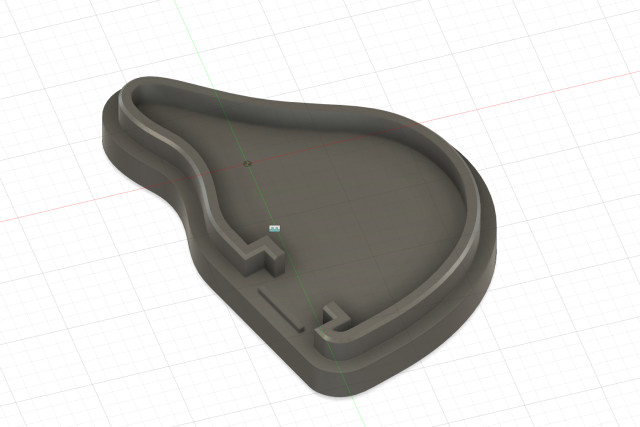
The replaceable faceplate is really cool! I need to learn how to use Fusion 360 too ><
Thank you!The replaceable faceplate is really cool! I need to learn how to use Fusion 360 too ><
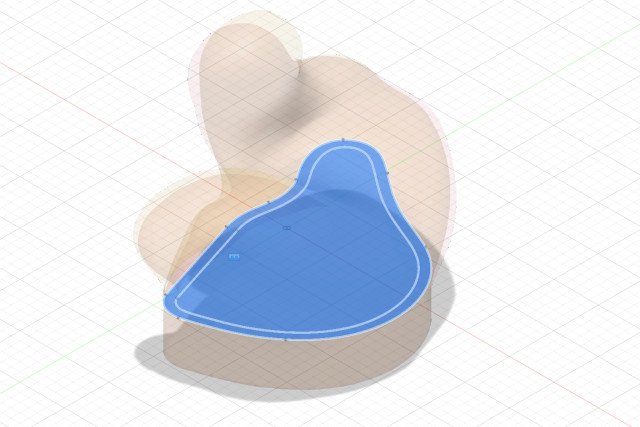
It's hard to explain all the features of the FUSION 360, but I first created a common sketch. I imported the model data on the left and the model data on the right, which was inverted, and drew a common geometric figure. All shells and faceplates are based on this sketch.
The technique of nail art is very helpful for how to make a face plate.
Two additional faceplates will be completed today or tomorrow. I will show you the photo again when it is completed.
I don't use glue on it. Only a kneaded eraser. I love the kneaded eraser.

All my IEMs are ready to be disassembled. If I don't like the sound, I can disassemble it and put the unit in another shell.
It is very convenient because it is easy to change the capacitor and replace the wiring for adjustment.
Last edited:
Thank you!
The technique of nail art is very helpful for how to make a face plate.
Two additional faceplates will be completed today or tomorrow. I will show you the photo again when it is completed.
I don't use glue on it. Only a kneaded eraser. I love the kneaded eraser.
All my IEMs are ready to be disassembled. If I don't like the sound, I can disassemble it and put the unit in another shell.
It is very convenient because it is easy to change the capacitor and replace the wiring for adjustment.
Kneaded eraser...do you mean blutak? o.O
mattmatt
100+ Head-Fier
- Joined
- Feb 11, 2012
- Posts
- 456
- Likes
- 282
Great! How did you manage to create the chamber/driver holder? Is it from a hollow shell?All IEMs have a common shape for the faceplate mounting area.
The face plate has a convex part that fits into the IEM.
Use a kneaded eraser when fitting to make it more difficult to remove. The kneaded eraser is a little sticky (but easy to peel off) so you can put it on and take it off again and again.
Synthesize common shapes.
The part where the face plate fits is all the same shape.

The kneaded eraser is a deformable eraser used in drawing.Kneaded eraser...do you mean blutak? o.O
Adhesiveness and hardness differ depending on the manufacturer.
I like Sakura Color Products RDD-150.
https://en.wikipedia.org/wiki/Kneaded_eraser
https://www.craypas.co.jp/products/eraser/034/0115/010715.html
Place the unit model on the external model.Great! How did you manage to create the chamber/driver holder? Is it from a hollow shell?
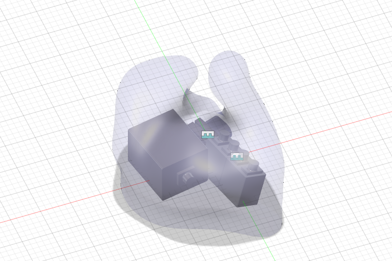
Create a sound path model.
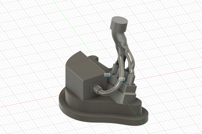
Subtract the sound path model from the external model.
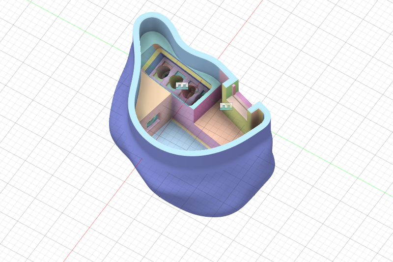
The unit model is made a little larger (0.1mm) than the actual one, so it feels like pushing the unit weakly. When assembling, fill the gap with a kneaded eraser to prevent sound leakage.
Does this explanation match?
Aldo40
Member of the Trade: Alambic-Ears
no you have to measure them even on the same platform, you cannot take a driver measure by someone and another driver measured by someone else. because the scale may not be the sameDo you know if I can find measurements online somewhere?
Aldo40
Member of the Trade: Alambic-Ears
First of all, it’s a great job , congratulationsPlace the unit model on the external model.
Create a sound path model.
Subtract the sound path model from the external model.
The unit model is made a little larger (0.1mm) than the actual one, so it feels like pushing the unit weakly. When assembling, fill the gap with a kneaded eraser to prevent sound leakage.
Does this explanation match?
 I don’t really understand the sticking with rubbing gum. Why don’t you create the locations in the full direct shell under 360 fusion? It would save you the trouble of assembling and pasting
thank you!First of all, it’s a great job , congratulationsI don’t really understand the sticking with rubbing gum. Why don’t you create the locations in the full direct shell under 360 fusion? It would save you the trouble of assembling and pasting
I'm using Google Translate, so you may have misunderstood your question. I'm sorry in that case.
The external model is mesh data.
FUSION 360 is not suitable for editing mesh data. Therefore, when editing the external model (smoothing, deformation, etc.), use meshmixer.
The sound path model is created as a geometric model. Geometric models can create accurate shapes and are suitable for repetitive editing. Therefore, the sound path model created by the geometric model at the end is converted to the mesh model and subtracted.
Aldo40
Member of the Trade: Alambic-Ears
thank you!
I'm using Google Translate, so you may have misunderstood your question. I'm sorry in that case.
The external model is mesh data.
FUSION 360 is not suitable for editing mesh data. Therefore, when editing the external model (smoothing, deformation, etc.), use meshmixer.
The sound path model is created as a geometric model. Geometric models can create accurate shapes and are suitable for repetitive editing. Therefore, the sound path model created by the geometric model at the end is converted to the mesh model and subtracted.
I use Google translate too lol So when you release the shell to the printer, they come out in one piece, is that okay?
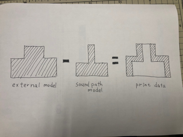
The sound path model is a solid model, not a hollow model.I use Google translate too lol So when you release the shell to the printer, they come out in one piece, is that okay?
The external model is also a solid model.
A hollow model can be created by subtracting the solid model from the solid model.
The sound path model is a solid model, not a pipe.
Since I received the message of the question, I will explain how to make a sunburst color face plate.
1) Create and print a face plate model with two steps in a staircase pattern.
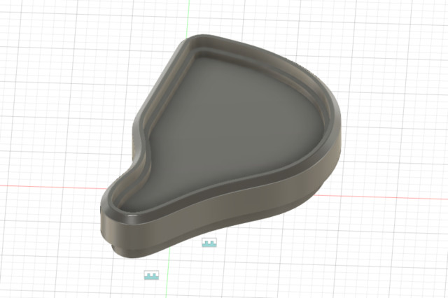
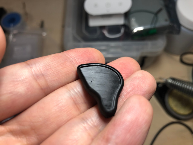
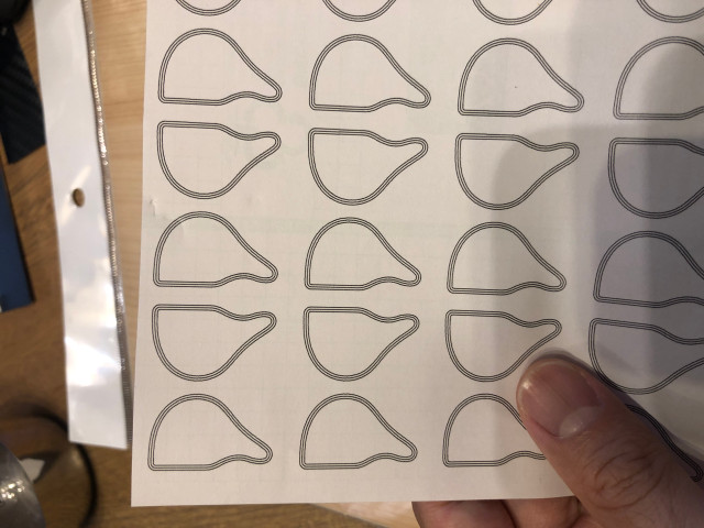
2) Draw a shape that goes into a deep step inside with illustrator and print it on the label sheet.
tips: You can create accurate shape data by saving the drawing data created by FUSION 360 as PDF and importing it into illustrator. It is good to offset the shape inward by 0.2 to 0.3 mm to make it smaller.
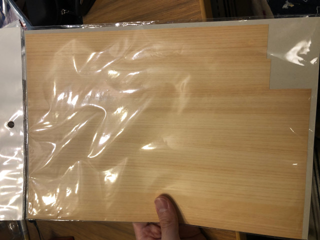
3) Attach the printed label sheet to a thin natural wood sheet and cut the natural wood sheet with a design knife. After cutting, remove the label sheet.
4) Use Illustrator to create a shape that fits into a shallow step on the outside. Use Illustrator or Photoshop to create black, red, and yellow gradients and logos. Print it on a transparent film (eg OHP film).
tips: Invert the characters.
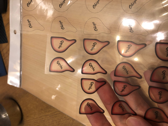
5) Cut the printed transparent film according to the outer diameter shape.
tips: Paint the cut section black with a felt-tip pen to make it less noticeable.
6) Stick a natural wood sheet on the base of the face plate.
7) Apply a thin layer of UV resin and cure.
8) Apply a thin layer of UV resin, attach a gradation film, and then apply UV resin.
9) It cures by exposing it to UV light.
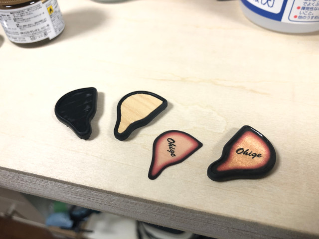
10) Apply UV resin to the entire surface to flatten the surface.
11) It cures when exposed to UV light,
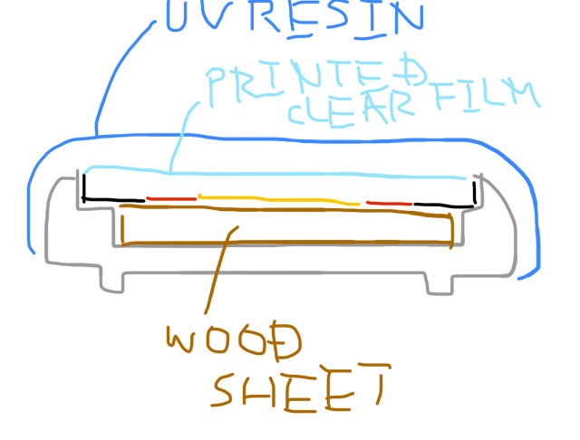
12) Paint with clear lacquer using an airbrush.
13) Take a closer look and enjoy yourself, and you're done!
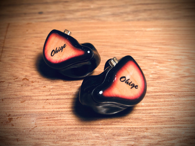
1) Create and print a face plate model with two steps in a staircase pattern.


2) Draw a shape that goes into a deep step inside with illustrator and print it on the label sheet.
tips: You can create accurate shape data by saving the drawing data created by FUSION 360 as PDF and importing it into illustrator. It is good to offset the shape inward by 0.2 to 0.3 mm to make it smaller.

3) Attach the printed label sheet to a thin natural wood sheet and cut the natural wood sheet with a design knife. After cutting, remove the label sheet.

4) Use Illustrator to create a shape that fits into a shallow step on the outside. Use Illustrator or Photoshop to create black, red, and yellow gradients and logos. Print it on a transparent film (eg OHP film).
tips: Invert the characters.

5) Cut the printed transparent film according to the outer diameter shape.
tips: Paint the cut section black with a felt-tip pen to make it less noticeable.
6) Stick a natural wood sheet on the base of the face plate.
7) Apply a thin layer of UV resin and cure.
8) Apply a thin layer of UV resin, attach a gradation film, and then apply UV resin.
9) It cures by exposing it to UV light.

10) Apply UV resin to the entire surface to flatten the surface.
11) It cures when exposed to UV light,

12) Paint with clear lacquer using an airbrush.
13) Take a closer look and enjoy yourself, and you're done!

Last edited:
I apologize for the continuous posting.
The new face plate is complete!
If I make an IEM for Vocaloid songs and anime songs, I would like to adopt it.
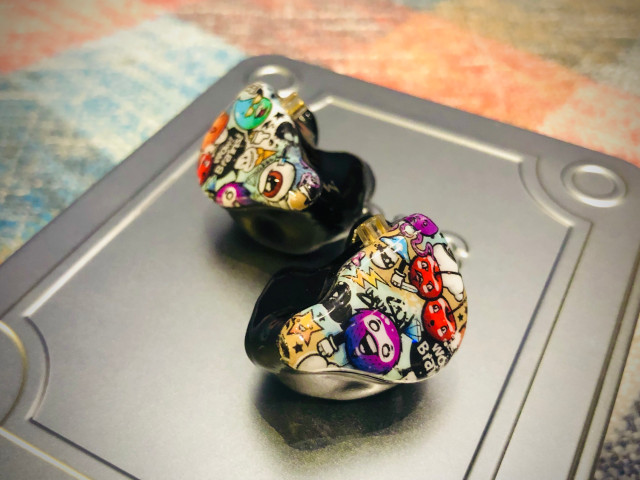
Cartoon typeA
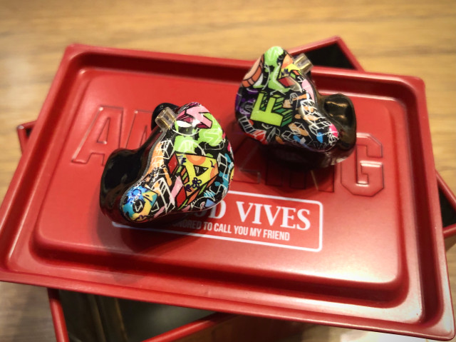
Cartoon typeB
The new face plate is complete!
If I make an IEM for Vocaloid songs and anime songs, I would like to adopt it.

Cartoon typeA

Cartoon typeB


