Home-Made IEMs
Jul 17, 2022 at 4:15 PM Post #14,161 of 15,974
Dunno about expert…😂 but, I will say that smaller ID(1-1.5mm) work to cut out the high frequencies. Larger ID (2-3mm) work to cut the lows. Length of tubing will heighten the effect but will also effect the output level along with phase if cut too long. Type of tubing also effects final FR. Industry norm is soft vinyl. However, if put in silicone, a different response is given. Manual manipulation of the FR has been used to great effect. In some ways its more effective with IEMs than electrical manipulation. However, for low frequency drivers, nothing beats a properly calculated L-Pad, which will lower overall volume of the driver without introducing a phase shift AND will eliminate a 2-3rd harmonic bump. Also, using MELF resistors greatly reduces overall THD. For high frequencies, a longer and wider tubing coupled with properly sized capacitor works wonders as well.
What an expert answer! :)
Thank!
 
Jul 18, 2022 at 1:30 AM Post #14,163 of 15,974
Speaking of L-pads, I did complete my previous Gk+RAB+38D1Xj but I’ve been distracted by the new arrival of my Mars 3. Damper options are currently a bit limited so may tweak again in future, but I’m really enjoying them as they are. I used an l-pad (3.2 series and 5.1 parallel I think) with the 38s in series. Oddly I had to reverse the polarity to get it to add to the bass of the GK. RAB has the standard zobel and MASM tubing and I added a 3.2 or 5.1R in series with everything. Very solid bass and very clear vocals (especially male). Thanks for all the tips guys
 
Jul 18, 2022 at 9:23 AM Post #14,164 of 15,974
And on the Mars 3, can any of the 3d printing gurus out there give any tips for how they print/slice their models?

Although my first prints were great without any supports or rotation, there were some minor details omitted from the connector area, so I played around with different orientations and support structures and haven’t yet found the perfect solution. I’m trying to print crystal clear and it is more difficult than I thought it would be. With supports on the outside, I can still see the dots after sanding so I assume you need to only attach supports to the base perimeter. That however puts the connector facing the build plate and so it loses some detail unless I put it at an angle. Is that how you guys do it? Will increasing the exposure help with the detail facing the build plate?

Also, close up I can see the layers at 50 microns even after sanding. Do I need to go down to 10 or 20 microns? Or just sand more?

Overall the printer has been excellent so far but going from excellent to perfect doesn’t seem easy.

Thanks!
 
Jul 18, 2022 at 12:40 PM Post #14,165 of 15,974
1.27mm spacing connectors. These are 13mm DD, 10mm planar, FED26859.
20211117_221815.jpg
Although maybe I'm looking at this thinking it works like loudspeakers where the larger the woofer is with all else equal the higher the sensitivity is.

So if I wanted to make it wireless I assume I want to maximize SPL/mW. Rigjt?
 
Jul 18, 2022 at 1:57 PM Post #14,166 of 15,974
And on the Mars 3, can any of the 3d printing gurus out there give any tips for how they print/slice their models?

Although my first prints were great without any supports or rotation, there were some minor details omitted from the connector area, so I played around with different orientations and support structures and haven’t yet found the perfect solution. I’m trying to print crystal clear and it is more difficult than I thought it would be. With supports on the outside, I can still see the dots after sanding so I assume you need to only attach supports to the base perimeter. That however puts the connector facing the build plate and so it loses some detail unless I put it at an angle. Is that how you guys do it? Will increasing the exposure help with the detail facing the build plate?

Also, close up I can see the layers at 50 microns even after sanding. Do I need to go down to 10 or 20 microns? Or just sand more?

Overall the printer has been excellent so far but going from excellent to perfect doesn’t seem easy.

Thanks!
When you are 3D printing, especially with liquid resin, you should almost ALWAYS have it tilted at an angle. Basically, the printer can only print surfaces that are connected. If the printer tries to print a surface that is not attached (ie floating) there is nothing for it to hold onto. Also, the resin you choose to use will also have a great effect on the final result.
i would recommend downloading an app called UV tools. Theres a resin cure test you can run that is honestly amazing. Also, I use Lychee Slicer. When I first started, the auto supports and island checker where LIFESAVERS.
 
Jul 19, 2022 at 1:58 PM Post #14,167 of 15,974
Guess I must have worded it all poorly. The point is that I want the non-driver components to not take up space inside the housing of the IEM so you can get more experimental with the inside of the IEM's housing itself. I don't really care HOW it's achieved, only that it's possible.

Edit: KInd of like the KZ E10
Looking at the KZ E10, wouldn’t something like the FiiO UTWS5 work?

It would not have a crossover/EQ, and the wireless would be over Bluetooth.
 
Jul 20, 2022 at 5:47 AM Post #14,168 of 15,974
When you are 3D printing, especially with liquid resin, you should almost ALWAYS have it tilted at an angle. Basically, the printer can only print surfaces that are connected. If the printer tries to print a surface that is not attached (ie floating) there is nothing for it to hold onto. Also, the resin you choose to use will also have a great effect on the final result.
i would recommend downloading an app called UV tools. Theres a resin cure test you can run that is honestly amazing. Also, I use Lychee Slicer. When I first started, the auto supports and island checker where LIFESAVERS.
Thanks, I've given Lychee and UV Tools a try now, and there is a lot more flexibilkity there than with Chitubox so lots to play with. The shells actually look really good but I was (possibly unrealistically) aiming for a glass look and every option and orientation seems to leave a minor imperfection somewhere. I think I need to keep the supports on the outside so the marks can be sanded away more easily and also to let the resin clear from the inside more freely. I may also need to improve my cleaning technique before curing.

Having said that, I may already have some that can be made clear with some sanding and lack.
1.27mm spacing connectors. These are 13mm DD, 10mm planar, FED26859.
That is some fantastic soldering. Very impressed!
 
Last edited:
Jul 21, 2022 at 12:12 AM Post #14,169 of 15,974
@stegeoc thanks, was not too bad after doing these... 4x32257 with 31736, one circuit has all the 32257 in series, the other is 2x2 series/parallel.
20210225_000343.jpg
 
Jul 23, 2022 at 9:06 AM Post #14,170 of 15,974
Snap29.pngSnap31.pngSnap42.png

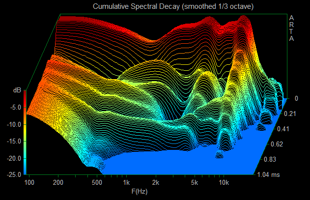
I spent another month for fine tunning this set of hybrid iem Low : tusq 10mm DD / Low_mid : sonion 37ap015 / mid_high : sonion 2389 / High : knowles 31736 This set of iem has been assembly / disassembly over 50 times, tube length has tried from short to long, crossing with various combination of damper / cap / resistor and this is the final setup that I can do.

My next attempt will also be DD hybrid, Low: 10mm PU DD / low_mid : Sonion 28uap / mid_high : Sonion E50DT / high : knowles 31736Snap38.pngSnap39.png


Finally I can fill the dip in 5kHz. The modi that I have made is re-adjusting the tubing length in the ratio of, bass=1 / mid=1.2 / high=2 , this ratio formula is previously posted by dhruvmeena96 in this thread. Further more, I have used bigger value of cap for 31736 replacing 0.33uf. The dip in 5kHz looks better now.
Snap1.png
Snap4.png


My hybrid config is low: tusq DD 10mm x1/ low_mid: sonion 37ap015 x1 / mid_high: sonion 2389 x1/ high: knowles 31736 x1
The FR looks close to VE8, VE8 consists of low: sonion 38am x1 / low_mid: sonion 37ap015 x1 / mid and high: knowles 32254 x2

Snap3.png
 
Jul 23, 2022 at 3:09 PM Post #14,171 of 15,974
.
Having said that, I may already have some that can be made clear with some sanding and lack.

That is some fantastic soldering. Very impressed!

On 3D printing with clear resin, to have a look like glass you had to sanded and varnish all the inner and outer hulls, you can dip the hulls directly into the varnish and then do the UV treatment.

For the orientation of the shell in shitubox or lychee, I put the nozzle up straight and I mount the 8mm piece and I apply the automatic support, and I remove the internal support and I print.
Each resin has its own properties so you have to adjust its settings by doing tests.
And you’re right, 3D printing isn’t as simple as it sounds:wink:
The most difficult is to print the clear hulls not tinted.
 

Users who are viewing this thread

Back
Top