Home-Made IEMs
Jan 17, 2019 at 7:01 AM Post #7,966 of 15,997
Ah, nevermind then, I mixed the them up. (I was thinking parallel with the driver)
Series FTW
@IvanNOON forget what i posted earlier
ok its cleared now right

both have its uses and i think parallel is easier to do for now. It will fix impedance....did an ltspice simulation and formulation is easy.

wait till knowles release detailed papers for series

Note:parallel notch filter means LCR are in parallel which make them work in series but will add specific component noise

series notch filter means LCR in series which is connected in parallel


well, One more thing, chitty store on aliexpress started selling 14.3mm planar magnetic speaker
and chitty store is reliable but they named this driver electrostatic by mistake
 
Last edited:
Jan 17, 2019 at 10:09 AM Post #7,967 of 15,997
Well one more issue i have to have a point on....
inverting the polarity may fix issues here and there, but is a bad practice

Not pointing out anyone, i myself do that on multi driver setup, which are hard to tweak

because, inverting polarity

1.may change the air load from front of driver(The BA ceiling) to inside of the BA(where voice coil resides) which can create more distortion as it move back as the air behind the driver has moved to in front of driver.

exception: only do with small driver like SWFK but also 2dB attenuation circuit(smaller drivers are less prone) and never do with vented driver as it can make your driver sound like the sound coming from vent

2. Imaging occurs when a pair BA successfully "projects" an audible representation of the instruments in focus front of us as they are compression driver by nature(exception are top nozzle format, i forgot the nomenclature used by Audio company like Knowles). When a BA is wired invertly, the information becomes out of focus, and sonically disorganized. This is especially true since the other drivers in the IEM are affected. Mid-range frequencies are present in the bass and tweeter drivers. Reversed wiring causes dynamic stereo information to "collapse," making the music lose much of its impact.

exception: @piotrus-g Dual CI and TWFK 2nd iteration and its children so far(replaced my low pass 72Hz CI with HODVTEC with vent open). There, inverting polarity was eminent as the Bass dB was so high and mid range would have been destroyed(bass Bleed thick). He actually reversed TWFK so reduced output from the TWFK woofer with reverse phase cancel some high dB bass bleed but also with crossover. and then he extremely high passed the tweeter of TWFK so, it sounds infocus rather than diffused.

3. High frequencies lose their focus when a BA is inverted. This results in an "airy" treble that causes the sound stage to sound larger (yet less defined). Although some desire this, it is inaccurate in the strictest sense. That is what a pseudo air is. The ceiling or top part of BA, becomes a spring which we never calculated, which is tighter, making BA throw focus inside the chamber and then relax like vented speaker, which comes out diffused and location less. that is, well what i call is lingering noisy air. Accurate air is recording Hiss.


Advantage and Disadvantage point

4. Cancellation: undesired cancellation is bad, and i mean very bad. Desired Cancellation can lead to good result.


Sealed driver is still okay with reverse polarity, but vented driver, if not tuned properly, can sound like hollow cup. So before reverting phase in multi driver, ask and confirm or simulate the design. or try and test with ear and dont see Freq graphs. You shouldn't feel weird imaging or feel that driver is forcing to keep up(yes, human ear can sense the movement of driver, just focus after designing)

Note : did with RAF and came with these points
 
Last edited:
Jan 18, 2019 at 12:41 AM Post #7,968 of 15,997
Hello again! I have been trying to finish up the electronical notch-filter and it has worked pretty well! My problem, however, is that the high frequencies gets affected aswell.
Here is a graph of the headphones before and after the use of the filter:


The changes from around 4-5kHz all the way to around 13kHz is quite alot.
I used a notch-filter calculator and the components I used was a polyester capacitor at 4.7uF along with an inductor of 560uH. The sound is good, but I wouldn't mind keeping more of the high frequencies to be able to tame them further with a screenfilter if needed.

I used this calculator: http://sim.okawa-denshi.jp/en/RLCBesample.htm

So, my question is this: Is there any other way of making this kind of a notch-filter without affecting the high-frequencies? Or can I modify the circuit to preserve it better?
I tried connecting the components in parallel, but it didn't do much difference at all (it only cut it 4-5db).

Thank you very much!

/Anders
using a notch filter like okawa-denshi(it is a bandstop and not a notch filter, so it is puting crossover inside a single driver with low and high pass), will definitely kill the treble. Use a series or parallel notch filter using an aircoil inductor. that is more accurate in damping notches.

for above circuit, that is plain circuit with sloping effect not mentioned in calculator properly.

you can use twin t notch filter

or a straight horn design if you are sticking with same driver
 
Jan 18, 2019 at 1:17 AM Post #7,969 of 15,997
IMG_20190118_114101.jpg
simple circuit design....with important para down...

Dual driver, with less load on drivers....but I know I passed to low for WBFK.....any help is welcome(especially for tube length)

No dampers by the way....

I need wfbfk on 2kHz as it doesn't have resonance there....
 
Last edited:
Jan 18, 2019 at 8:31 AM Post #7,970 of 15,997
simple circuit design....with important para down...

Dual driver, with less load on drivers....but I know I passed to low for WBFK.....any help is welcome(especially for tube length)

No dampers by the way....

I need wfbfk on 2kHz as it doesn't have resonance there....
22uF is way too much. I would recommend 4.7uF-0.47uF range.
And, if I remember correctly, RAB is louder so you would need to attenuate (probably, not sure)
 
Last edited:
Jan 18, 2019 at 10:36 AM Post #7,971 of 15,997
22uF is way too much. I would recommend 4.7uF-0.47uF range.
And, if I remember correctly, RAB is louder so you would need to attenuate (probably, not sure)
The moment I add a series notch(read pars below)the ran will attenuate itself and zobel circuit will smoothen the treble range.

The problem is WBFK. I need to cross a WBFK so that it covers the RAB 2kHz peak and cover some good amount of treble extension...

Well I am thinking of removing WBFK now.

RAB seems good in itself.

RAB and RAF are pretty same, so now I think I am changing back to my favourite RAF with Libby horn folded to boost 2kHz.


This is my design

I need an experienced person to help me.

At what length, the reverse phase will spin totally to normal phase.


The bell wire act as low pass and the damper only pass extremely low.

I have to calculate the resonator tube, the series resonator have been designed for both side..


IMG_20190118_205630.jpg
 
Jan 18, 2019 at 10:56 AM Post #7,972 of 15,997
The issue is, how I am gonna fit that driver.
The back tube is damped, because I dont want messed up air pressure in front. I need pure LF from back end to reinforce front end, just to extend low end. Second, the tiny hole in LF back resonator reduces ear pnematic pressure inside the ear plus leaks the HF inside ear canal.

Front Resonator is simple pre peak damping, as folded horn induces peaks. It acts as throat horn. The tube coming out from throat resonator is Helmholtz resonator with straight length (expanding cavity less). I have to tune it for specific low end boost.

All low end boost is done in sub bass region. I need pure sub bass. Below 50Hz.

I want to reach pure planar magnetic audeze LCD4 style bass from BA
 
Jan 18, 2019 at 11:20 AM Post #7,973 of 15,997
This is my design

I need an experienced person to help me.

At what length, the reverse phase will spin totally to normal phase.


The bell wire act as low pass and the damper only pass extremely low.

I have to calculate the resonator tube, the series resonator have been designed for both side..


That's quite an undertaking.
My advice would be to test everything step-by-step.
Start with just front volume into a straight tube, tune it properly. Then add horn, tune it. Then the helmholz, etc.

BA tuning is very unpredictable, so starting with the least amount of variables as possible helps a lot in figuring out their behaviour.
 
Jan 18, 2019 at 12:04 PM Post #7,974 of 15,997
That's quite an undertaking.
My advice would be to test everything step-by-step.
Start with just front volume into a straight tube, tune it properly. Then add horn, tune it. Then the helmholz, etc.

BA tuning is very unpredictable, so starting with the least amount of variables as possible helps a lot in figuring out their behaviour.
Well I will take your suggestion....
BA are crazy to tune.

But if I am able to do this, then it would be a breakthrough.

I have done zobel, perfect notch(no treble kill), TAEC style resonator and Libby horn(4mm wide continuous flow) in 2017

And my setup was for my old uncle as a hearing aid, with RAB and plug to play music.

He said that my setup was league above any hearing aid he has tried. He can listen to ambience of nature, what he told me.

The problem was blackness. The convertor, Bluetooth may be inferior but I think my design may be increasing the HF way to much.

Now I will try that in IEM. I have to perfect dual chamber resonator, back wave reinforcement and parallel/adjacent Helmholtz tubing.
 
Last edited:
Jan 18, 2019 at 1:43 PM Post #7,976 of 15,997
Good luck, man. Here's something that might be helpful:

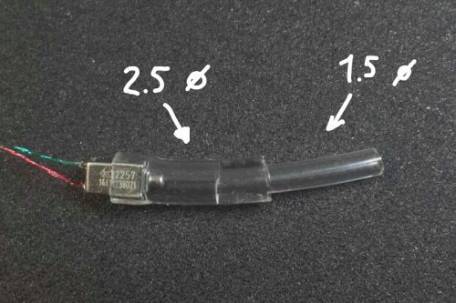
RAB fits perfectly into 2.5mm ID tubing. Might work for the front resonator.
Yup, but make sure to get sweet spot in resonator length.

That is what i call reverse horn effect.

Note:If you turn this design other way round, it will increase the peaks.
This way, we damp the peaking effect in simple.
Then designing a horn to stably and linearly boost treble..

Yes it will work as Series Resonator or simply TAEC. Add a zobel and you will get a godly level smooth treble. So smooth that it can intoxicate you. But don't expect extension since these methods only damps. No need to add a damper, if you get zobel and series resonator right

Dampers are quick fix and has a lot of drawbacks for imaging. Plus using single driver, the dampers deteriorate the acoustic info by diffusing and damping it.

Campfire Andromeda has no damper on TAEC. That's the secret for Andromeda huge stage(bigger than spiral ear se5 u).

Zobel will just shape the treble for better and fix high freq phases.

Can add any of the notch filter to peak down BA impedi g resonance.(always do calculation from impedance graphs).

Perfect mids.
 
Last edited:
Jan 19, 2019 at 5:23 AM Post #7,978 of 15,997
simple circuit design....with important para down...

Dual driver, with less load on drivers....but I know I passed to low for WBFK.....any help is welcome(especially for tube length)

No dampers by the way....

I need wfbfk on 2kHz as it doesn't have resonance there....
That is 2.2uF now.

no it is 0.47uF.. thats right

RAB cahnged to RAF. RAF has more bass
 
Last edited:
Jan 19, 2019 at 4:24 PM Post #7,979 of 15,997
Hello everyone, I'm making a set of CIEMs for my brother. It's the first time I'm doing for someone else, so I can't insert the impressions in my ear to see if they fit are good :grin:

After cutting and sanding the impressions it seems that the canal got a little short comparing with mine. I've duplicated the impression with the same material before cutting and sanding, so I still have the original.

Here are some pictures of the original impression with the one that I've worked, can anyone point to me if I've cut too much the canal and if the direction of the cut is right?

IMG_2984.JPG IMG_2985.JPG IMG_2986.JPG IMG_2987.JPG IMG_2988.JPG
 
Jan 20, 2019 at 3:40 AM Post #7,980 of 15,997
I don’t have too much experience, but I think you did good. The inner part of the canal is not that important for sound in my experience. You just have to make sure the holes do not touch the canal, other than that the influence on the sound seems minimal at best.

How did you do the copies of the impressions, did you use agar for the negatives?
 

Users who are viewing this thread

Back
Top