tomb
Member of the Trade: Beezar.com
- Joined
- Mar 1, 2006
- Posts
- 10,891
- Likes
- 1,066
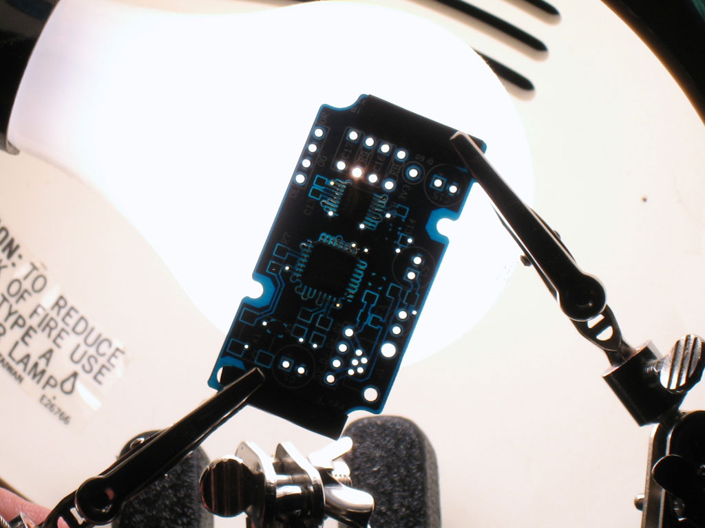
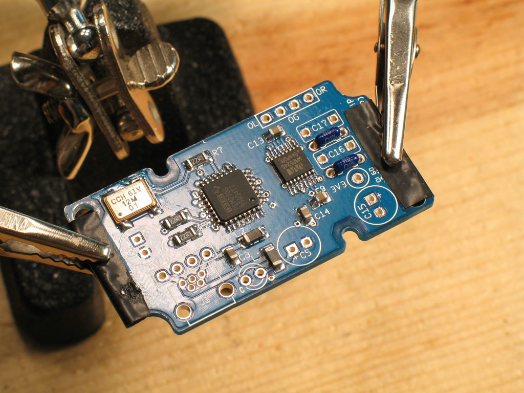
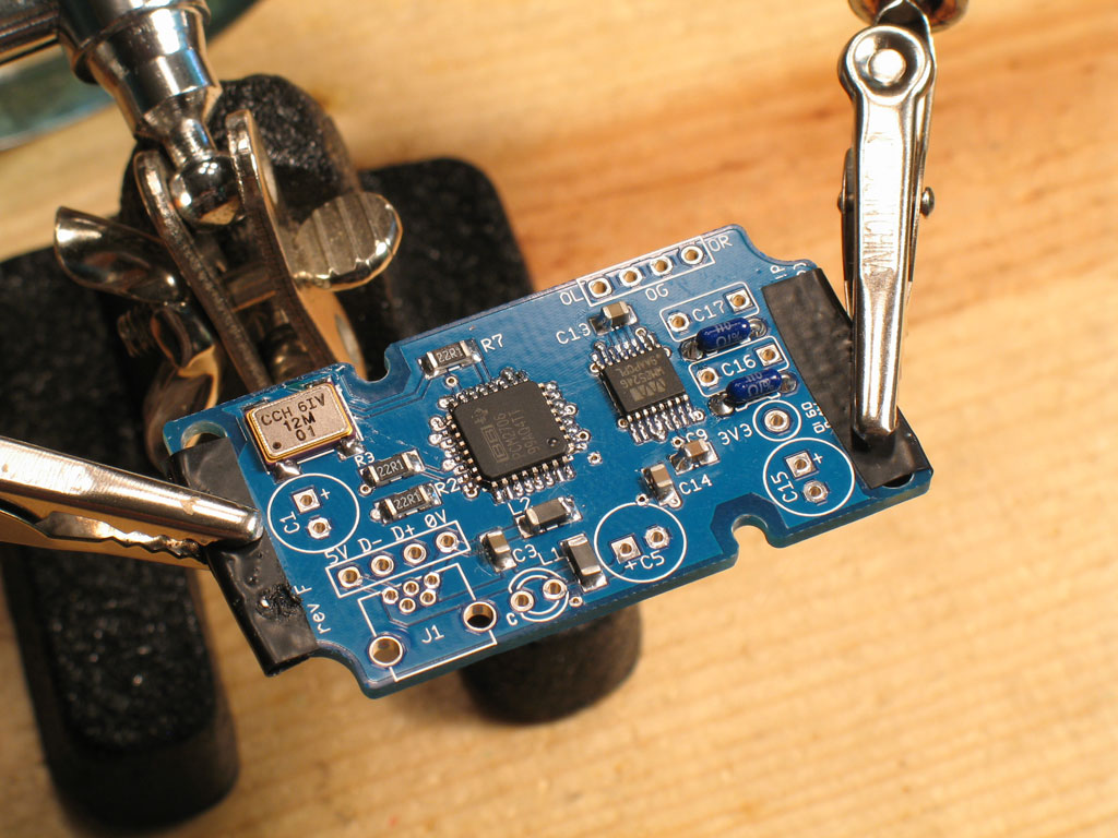
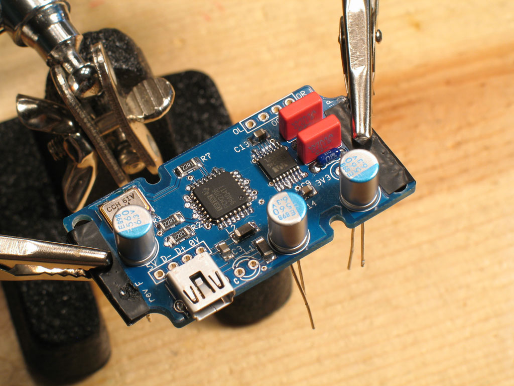
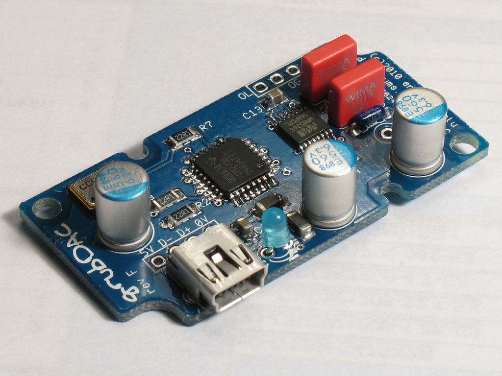
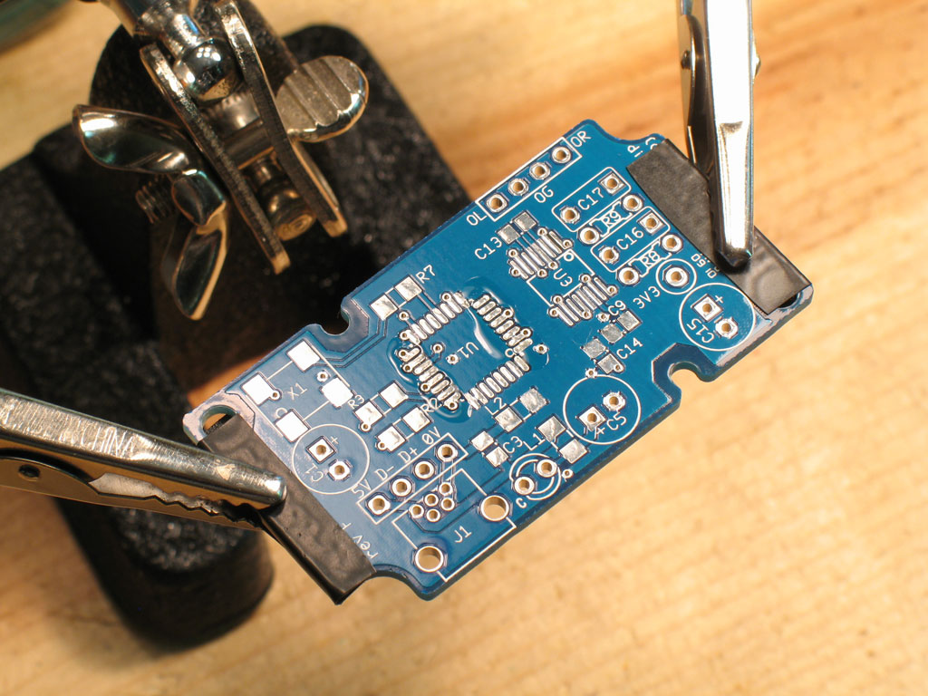
Cobaltmute's new GrubDAC was originally designed in conjunction with Joneeboi's new Carrie USB-powered portable amp. However, it has all of the same uses as the BantamDAC - stand-alone, CableDAC, Millett MAX and MOSFET-MAX. The PCB's have been shipping for awhile and we hope to have kits available soon, so perhaps a step-by-step build thread will prove useful.

To many of you, SMD soldering is something new and perhaps a little bit scary.
However, with the right preparation and strategy, you may find it easier in some
respects than through-hole soldering. Like any Do-It-Yourself exercise, success
depends a great deal on proper preparation and tools. SMD has some special traits that make a few tools (one in particular) absolutely necessary.
Here's a list of things you may want, with the first couple almost a necessity:
Tweezers cannot be over-emphasized. Without a good pair, I have trouble imagining how manual SMD-soldering can even be accomplished. Get a good pair! I use a pair of ESD-safe, bent tip tweezers that I bought at Fry's, but all the good DIY-suppliers have them in stock - Mouser, DigiKey, Allied, Newark, etc. Here's the pair that I use:

Another device that you may find useful is the flux pen. The flux goes down as a
thick liquid and gets sticky very quickly - almost sticky enough to hold a part in
place. The pen form lets you apply the flux where you want it, even on a very small
SMD PCB. I like Kester and stick with their products. The one I use is the Kester
#186. It contains regular activating flux that works great (no water-soluable or
no-clean flux for me).
Finally, and this varies with the individual, I use a Hakko 936 soldering station, set
at 325 deg.C. with a 0.8D chisel tip - 900M-T-0.8D. This is a half-size chisel tip of
the standard tip that comes with the Hakko 936 (900M-T-1.6D). Solder is the same
solder that I use for all my DIY stuff: Kester 44 eutectic, 63/37, 0.025" diameter.
Larger is too big for SMD IMHO, and smaller stuff breaks all the time.
Be sure to review the GrubDAC website and please check out Tangent's excellent
tutorial on SMD soldering: http://www.tangentsoft.net/elec/movies/tt03.html .
To many of you, SMD soldering is something new and perhaps a little bit scary.
However, with the right preparation and strategy, you may find it easier in some
respects than through-hole soldering. Like any Do-It-Yourself exercise, success
depends a great deal on proper preparation and tools. SMD has some special traits that make a few tools (one in particular) absolutely necessary.
Here's a list of things you may want, with the first couple almost a necessity:
- tweezers
- flux pen
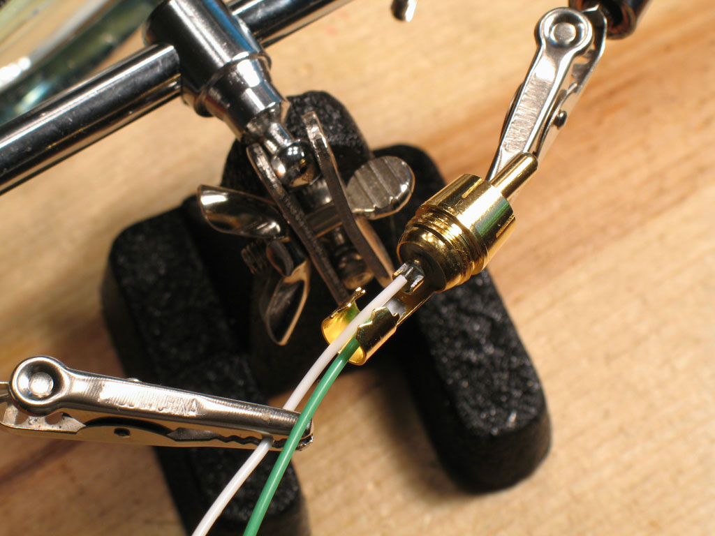
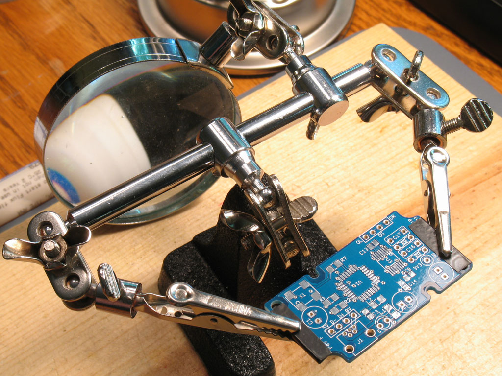
- helping hands
- small-diameter solder
- small-tip soldering iron
Tweezers cannot be over-emphasized. Without a good pair, I have trouble imagining how manual SMD-soldering can even be accomplished. Get a good pair! I use a pair of ESD-safe, bent tip tweezers that I bought at Fry's, but all the good DIY-suppliers have them in stock - Mouser, DigiKey, Allied, Newark, etc. Here's the pair that I use:
Another device that you may find useful is the flux pen. The flux goes down as a
thick liquid and gets sticky very quickly - almost sticky enough to hold a part in
place. The pen form lets you apply the flux where you want it, even on a very small
SMD PCB. I like Kester and stick with their products. The one I use is the Kester
#186. It contains regular activating flux that works great (no water-soluable or
no-clean flux for me).
Finally, and this varies with the individual, I use a Hakko 936 soldering station, set
at 325 deg.C. with a 0.8D chisel tip - 900M-T-0.8D. This is a half-size chisel tip of
the standard tip that comes with the Hakko 936 (900M-T-1.6D). Solder is the same
solder that I use for all my DIY stuff: Kester 44 eutectic, 63/37, 0.025" diameter.
Larger is too big for SMD IMHO, and smaller stuff breaks all the time.
Be sure to review the GrubDAC website and please check out Tangent's excellent
tutorial on SMD soldering: http://www.tangentsoft.net/elec/movies/tt03.html .

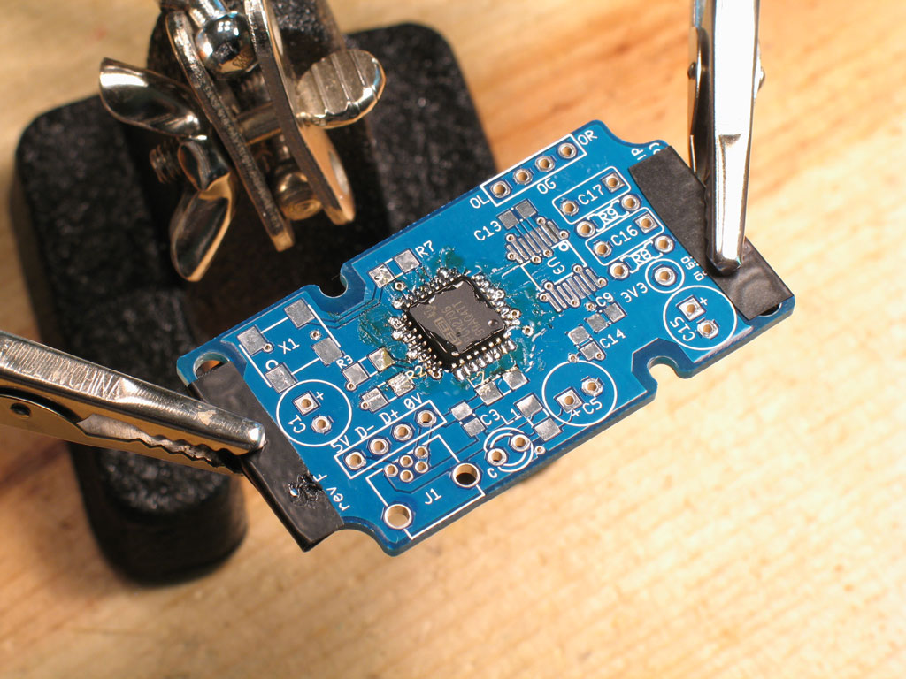
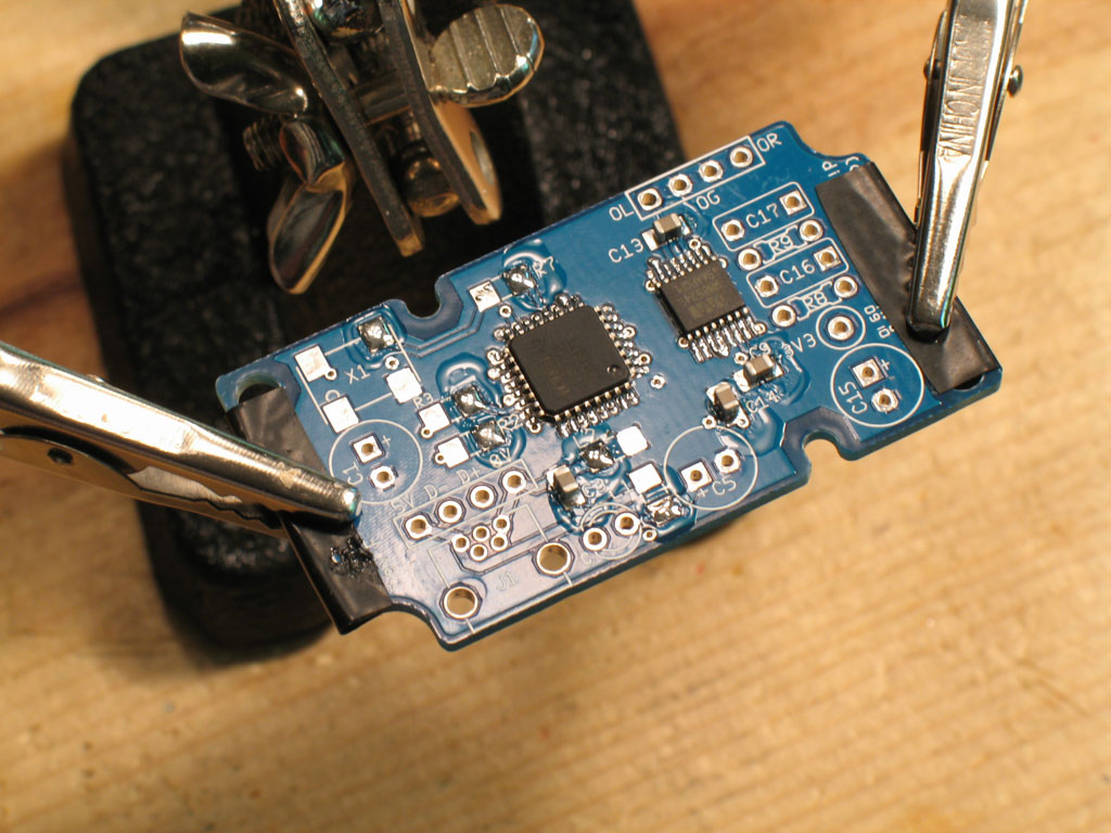
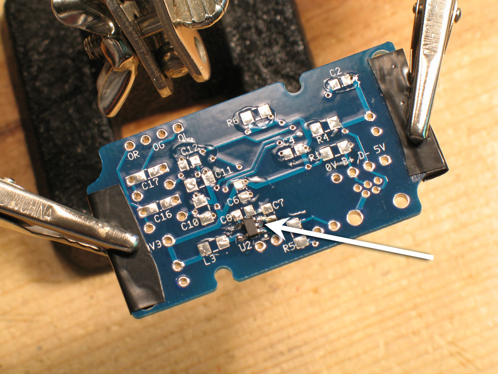
") I apply a tiny bit of solder to the tip of the iron, then touch it to each pin, repeating as necessary. It works fine.
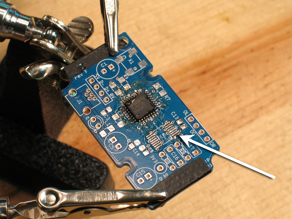
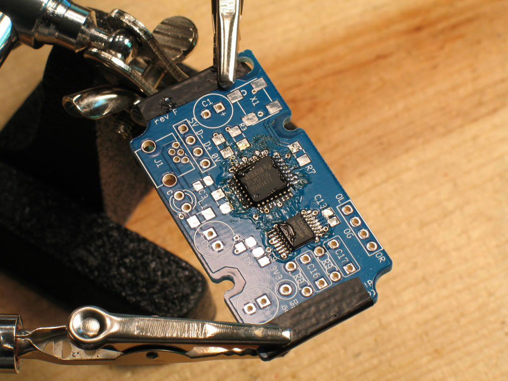
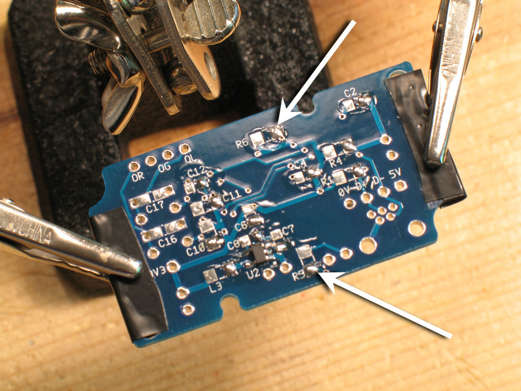
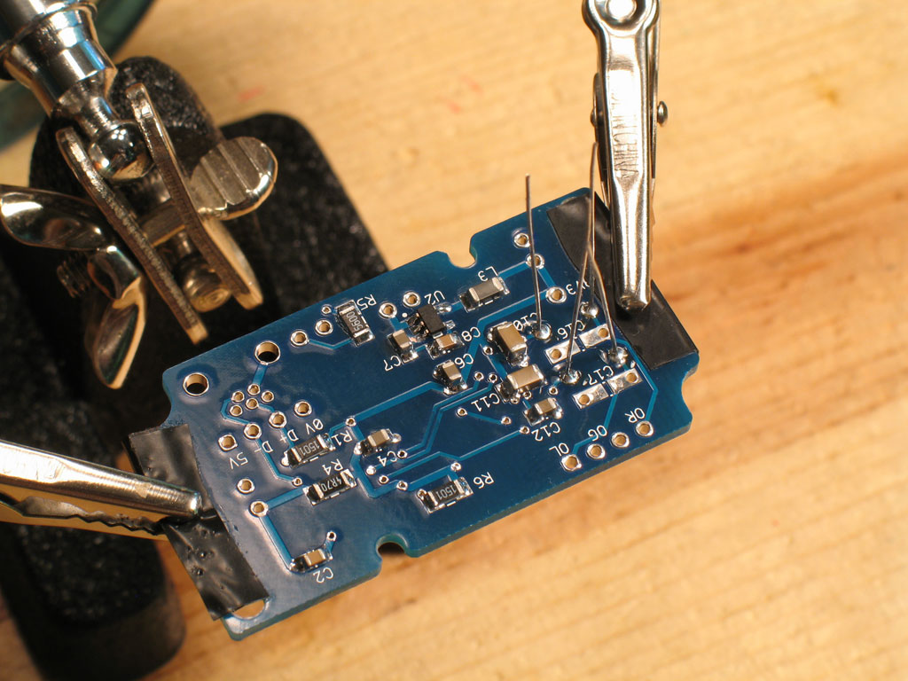
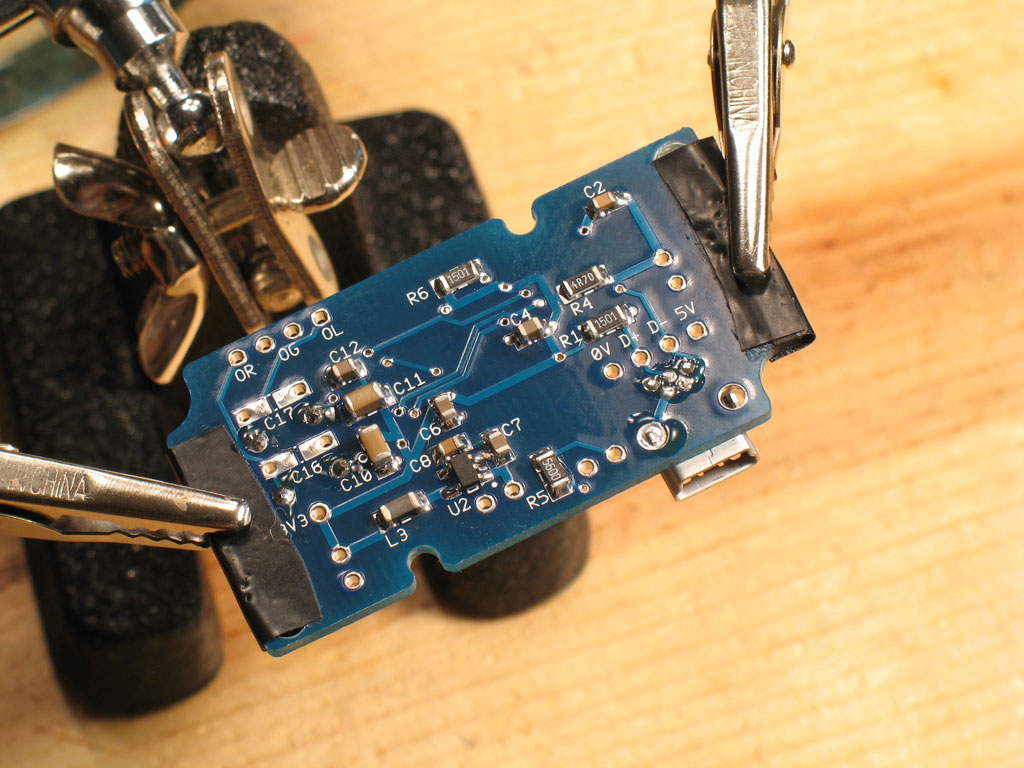
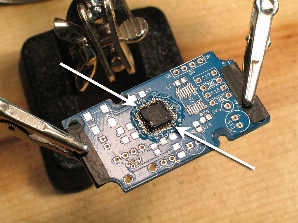
I apply a tiny bit of solder to the tip of the iron, then touch it to each pin, repeating as necessary. It works fine. ") Use more flux as necessary - it burns off fast. For the top and bottom sides, I simply rotated the helping hands. Note however, that some of the electrical tape got melted doing that. This is because even though I was almost soldering pins individually, I was still holding the iron horizontal and using the down-and-wipe method to finish off the solder on the pins.
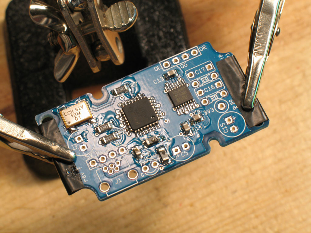
Use more flux as necessary - it burns off fast. For the top and bottom sides, I simply rotated the helping hands. Note however, that some of the electrical tape got melted doing that. This is because even though I was almost soldering pins individually, I was still holding the iron horizontal and using the down-and-wipe method to finish off the solder on the pins.